
Watertight Electrical Connector (1961)
U.S. Patent No. 2,991,441, granted on July 4, 1961, to Francis E. Butler and Sylvan Wolf, protects a specialized electrical connector designed for extreme underwater environments. Developed for the U.S. Navy, this device was primarily intended for use with underwater mines (drill mines or signal mines) at depths of up to 400 feet.
The primary challenge addressed by this invention was twofold:
- External Sealing: Preventing high-pressure seawater from entering the mine at the connection point.
- The “Water Stop”: Preventing water from traveling through the inside of the cable and into the mine if the cable’s outer jacket were to break or be severed.
Key Components and Design
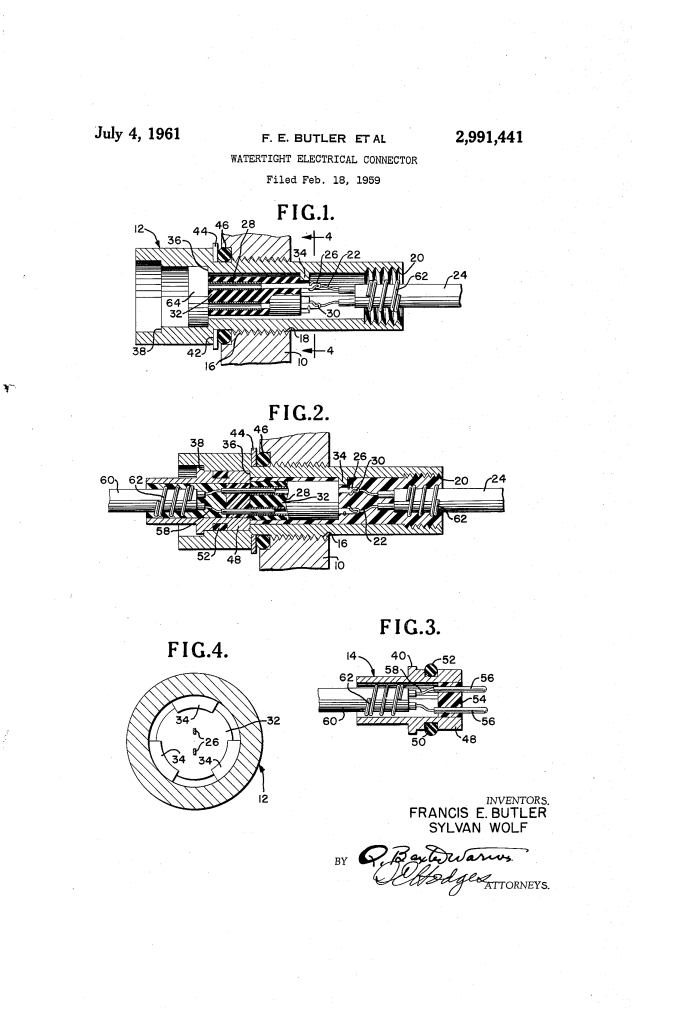
The connector consists of a Female Section (12), which is threaded directly into the mine wall, and a Male Section (14), which friction-fits into the female sleeve.
- O-Ring Seals: Two distinct O-rings provide the primary physical barriers. One (46) seals the female section against the mine wall (10), and another (52) seals the interface between the male and female sections.
- Epoxy Resin Potting: The interior of both sections is filled with an epoxy resin potting compound. This liquid resin is poured into the connector during assembly and hardens to create a solid, insulating, and watertight block.
- Wire Coils (62): A unique feature of this design is a wire wrapped tightly (three full turns) around the cable ends before potting. These coils, combined with interior threads (20) in the sleeve, ensure the cable is mechanically locked to the connector and cannot be twisted or pulled out.
How the “Water Stop” Works
Traditional connectors often fail if the cable is damaged elsewhere, as water can be forced through the gaps between individual wires (the “wicking” effect) by high hydrostatic pressure.
In this patent, the potting compound completely embeds the uninsulated portions of the wires, the pins (56), and the tubes (28). Because the epoxy fills every microscopic void within the connector sleeve, it creates an impenetrable “water stop.” Even if the cable is severed and the interior of the cable is flooded, the solid epoxy block prevents the water from reaching the intricate machinery inside the mine.
Technical Specifications Summary
| Feature | Description |
| Max Depth | 400 feet (High-pressure resistance) |
| Material | Cylindrical sleeve with Bakelite insulating plugs |
| Seal Mechanism | Dual O-rings + Epoxy Potting |
| Mechanical Lock | Interior threads and tightly wrapped wire coils |
| Primary Use | Naval underwater mines and signal devices |
Comparison of Male and Female Sections
| Female Section (Mine Side) | Male Section (Cable Side) |
| Houses Tubes (28) to receive pins. | Houses Contact Pins (56). |
| Threaded externally to mount to mine wall. | Fits into the female section via friction. |
| Uses a washer (44) to protect the O-ring. | Uses an exterior groove (50) for its O-ring. |
Summary of Claims
The patent claims a connector where:
- The electrical connections are entirely embedded in insulating potting means (epoxy).
- Wire coils are wrapped around the cable ends to provide mechanical stability and enhance the watertight seal.
- The potting engages each turn of the coil to secure the cable end to the connector body, ensuring no movement even under high pressure.
