
Window and Railway Car Ventilator (1895)
U.S. Patent No. 534,322, granted on February 19, 1895, to John Thomas Darkins (later corrected in official records to Dorkins), describes a specialized mechanical ventilation system designed to provide a continuous supply of fresh air while simultaneously preventing the entry of rain, dust, cinders, and insects. Darkins, an inventor residing in Allegheny, Pennsylvania, engineered this device to function effectively in both stationary buildings and moving vehicles like railway cars and vessels.
This specific invention solved a persistent problem in late 19th-century transportation and urban architecture: how to open a window or cabin to fresh air without letting in the heavy soot, coal cinders, and driving rain common to the era’s coal-powered rail travel and urban environments.
The Innovation: The “Interfering Partition” System
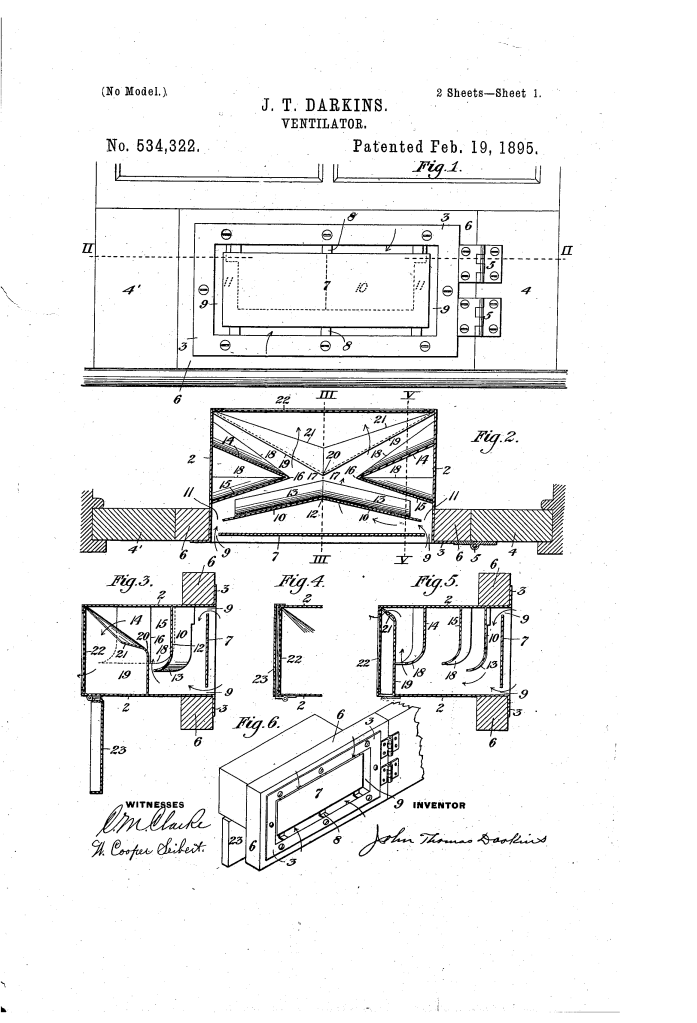
The brilliance of the Darkins ventilator is its utilization of a complex, multi-layered maze of internal deflecting plates and baffle walls set at alternating angles. Instead of relying on a simple open grate, this invention forces incoming air to travel through a tortuous, winding path.
Because heavy particulates like cinders and raindrops have more momentum than air molecules, they cannot make the sharp, high-velocity turns required to navigate the internal maze. Instead, they slam into the deflecting walls and drop harmlessly to the bottom of the casing, while the clean air continues into the room or vehicle cabin.
Why the Curved Flanges?
- Aerodynamic Flow: Every internal partition features an edge that is systematically bent under or over in a rounded curl away from the incoming air stream. This eliminates sharp edges that would cause micro-turbulences and restrict airflow.
- Debris Capture: The curved edges act as tiny gutters that catch traveling soot or rain droplets and funnel them downward into a collection zone at the base of the container, where they can be easily cleaned out over time.
Key Structural Components
The composition of the ventilator relies on a highly scientific spatial arrangement where each internal plate serves a distinct aerodynamic or filtration purpose:
| Component | Function |
| Outer Casing (2) | The main rectangular shell, constructed of light sheet metal, housing the internal components. |
| Front Diaphragm (7) | A solid plate set slightly back from the front face, creating a narrow surrounding perimeter space (11) that acts as the initial intake valve. |
| Receding Partition (10) | Suspended from the top, its walls recede toward the center to pinch and accelerate the airflow inward. |
| Converging Walls (14 & 15) | Two vertical walls that meet at a sharp apex (16), leaving a narrow central gap (17) to further compress the air currents. |
| Full-Length Partition (19) | Secured to the bottom of the case, it rises up directly behind the apex gap, blocking any direct line-of-sight path for debris. |
| Wire-Gauze Screen (22) | Covers the delivery side of the case to catch fine insects or light ash that cleared the baffles. |
| Hinged Hood (23) | A solid exterior shutter that can be swung upward to completely seal the ventilator shut during severe storms. |
Dual Application Modes
Darkins engineered two distinct physical layouts for his system depending on whether it was deployed for domestic or transit use.
1. Stationary Service (The Window Assembly)
For buildings, the ventilator is attached to a swinging block hinged to a set of partition blocks. This entire assembly fits snugly between the window sash and the sill, filling the gap perfectly. Because it functions identically in reverse, installing a second unit on the opposite side of a room creates a natural induction and eduction (exhaust) system, drawing fresh air in through one side and pulling foul air out the other.
2. Railway Service (The Suction Exhaust)
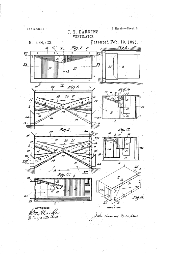
For moving trains, the design adapts to exploit the vehicle’s high speed. Installed just under the upper roof deck of a railcar, the diaphragm is replaced with an intake funnel featuring flaring lips. As the train rushes forward, external air blasts into the funnel, creating a powerful venturi effect inside the casing. This pressure drop acts as a vacuum, aggressively sucking the rising foul and heated air out of the passenger car.
The Manufacturing & Assembly Sequence
To assemble the stationary window variant of the ventilator, the component paths are aligned in a strict sequence:
- Form the outer rectangular sheet metal casing with integrated mounting flanges.
- Suspend the front diaphragm and the angled receding partitions from the upper casing plate.
- Rivets or solder the converging walls into place so they meet precisely at the central apex.
- Anchor the full-length partition to the bottom plate, ensuring its curved upper flanges face away from the primary draft.
- Secure the fine wire-gauze screen across the rear delivery face.
- Hinge the protective exterior hood to the lower casing rim and mount the entire unit onto the wooden window partition block.
Summary of Patent Claims
The patent explicitly claims:
- A window ventilator comprising a rectangular box containing a front diaphragm, a perforated screen, and intervening flanged baffle partitions.
- A specialized window installation framework featuring a swinging block hinged to a partition block that entirely fills the open space under a raised window sash.
- A specific architectural layout of alternating partitions consisting of a top-suspended partition receding toward the center, dual partitions converging to an apex, and a bottom-anchored partition that diminishes in height toward the center.
- A transit-specific variant for moving vehicles utilizing internal funnels and top-open partitions configured to induce a vacuum draft via the external motion of the vehicle.
