
Valve Indicator (1891)
U.S. Patent No. 450,451, granted on April 14, 1891, to Frank J. Ferrell, addresses a common frustration in 19th-century plumbing and steam engineering: the inability to tell exactly how far a valve is open just by looking at it.
Ferrell, an inventor based in New York City, developed a precision indicating device that could be attached to a standard globe valve. This allowed engineers and firemen to see the “exact amount of opening” at a glance, moving away from the guesswork of counting manual turns of a handwheel.
The Innovation: The “Sliding Spline” Gear System
The technical challenge Ferrell solved was how to link a stationary dial to a valve stem that moves in two different ways—rotating and sliding (longitudinally) as it opens.
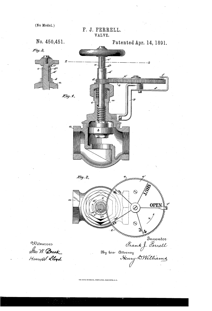
1. The Keyway and Sleeve (c’, d’)
Ferrell cut a longitudinal groove, or “keyway,” into the upper part of the valve stem. A sleeve with a small projecting stud (spline) fits over the stem. As the stem rotates, the stud forces the sleeve to rotate with it; however, as the stem moves up or down, the stud simply slides in the groove. This allows the gear to capture the rotation of the valve without being pushed up or down by its stroke.
2. The Reduction Gear (d, e)
The sleeve is attached to a small pinion gear (d). This small gear meshes with a much larger gear-wheel (e). This gear reduction is calibrated so that the full travel of the valve (from closed to wide open) results in less than one full rotation of the large dial, ensuring the reading never “overlaps” itself.
3. The “Brilliant” Indicator Plate (e’)
Attached to the large gear is a marked disk. As the valve is turned, the disk rotates under a fixed index (f), pointing to markings such as “Open,” “1/4,” “1/2,” and “3/4.”
Key Technical Components
The device was designed to be robust enough for high-pressure steam environments while remaining simple to manufacture:
| Component | Function |
| Valve Stem (c) | The threaded rod that operates the valve; modified with a groove (c’) that never enters the packing. |
| Toothed Pinion (d) | The “driver” gear that sits loosely on the stem but rotates in unison with it. |
| Large Gear-Wheel (e) | The “follower” gear that holds the indicating markings and provides the scale. |
| Indicating Plate (e’) | The visual dial marked with fractional divisions of the valve’s stroke. |
| Fixed Index (f) | A stationary pointer attached to the casing that indicates the current reading. |
| Support Arm (g) | A bracket extending from the valve casing that holds the indicator assembly in place. |
Precision and Safety
Ferrell’s design included several “fail-safe” engineering choices:
- Packing Protection: The groove in the valve stem is carefully measured so that it never reaches the “packing” (the seal that prevents leaks). If the groove entered the packing, it would create a gap, causing the valve to leak high-pressure fluid or steam.
- Positive Operation: Unlike friction-based indicators, the gear-and-spline system is “positive,” meaning it cannot slip. If the valve moves, the dial must move.
- Universal Application: The device was designed so it could be retrofitted onto “any ordinary valve” with only minor modifications to the stem, making it a highly marketable industrial upgrade.
About the Inventor: Frank J. Ferrell
Frank J. Ferrell was a New York-based inventor active during the height of the American Industrial Revolution.
- Focus on Control: Ferrell’s work often focused on the refinement of steam and fluid power. During this era, precision was becoming vital as steam engines and boilers became more powerful and prone to explosion if not monitored correctly.
- Efficiency: By providing a visual “Open” to “Closed” scale, Ferrell allowed for better “throttling” of engines, which saved fuel and prevented wear and tear on machinery.
- Legacy: The principle of the gear-driven valve position indicator is still used today in industrial settings, though often replaced by electronic sensors in modern “smart” factories.
Summary of Claims
The patent explicitly protects:
- The combination of a rotating/sliding valve stem with a toothed pinion fitted loosely upon it.
- The sliding stud-and-groove connection that allows the stem to move vertically without moving the gears.
- A flange on the pinion that sits between the gears and the casing to prevent any longitudinal movement of the indicating mechanism.
- The use of a large gear-wheel and fixed index to provide a fractional reading of the valve’s position.
