
Vacuum Pump; David N. Crosthwait, Jr.; 1,947,204
The patent by David N. Crosthwait, Jr. of Marshalltown, Iowa, describes a Vacuum Pump of the jet exhauster type (Patent No. 1,947,204). This invention is a high-efficiency fluid-moving machine that combines a liquid jet with a high-speed centrifugal impeller to evacuate air or gases from a chamber, creating a powerful vacuum without the need for heavy, traditional pistons or valves.
The “Why”
In the early 1930s, vacuum pumps used in large-scale steam heating systems were often bulky, inefficient, and prone to losing their “prime” (the liquid needed to start the pumping action). Crosthwait identified a pain point in the energy loss associated with traditional jet exhausters. By adding a rotating element to a standard jet stream, he aimed to “atomize” the liquid, vastly increasing the surface area available to trap and carry away air molecules, thereby creating a deeper vacuum with less power.
The Inventor: David N. Crosthwait, Jr.
David N. Crosthwait, Jr., a titan of 20th-century mechanical engineering, specialized in making buildings “breathe.” His engineering philosophy focused on integrated simplicity: why have a separate pump and a separate exhauster when one rotating shaft can do both? This patent exemplifies his ability to merge two distinct physical principles—centrifugal force and jet entrainment—into a single, compact unit.
Key Systems Section
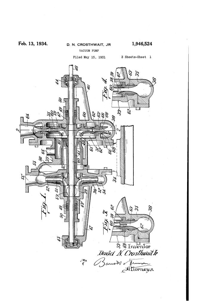
Centrifugal Jet Impeller
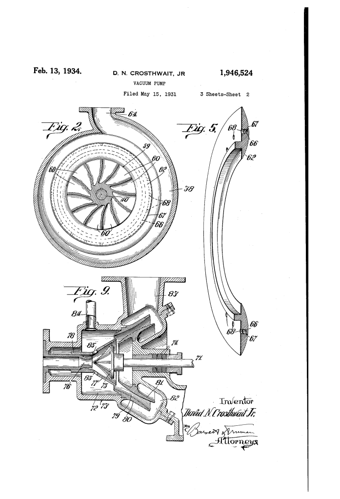
- Radial Dispersion: A stream of “motor liquid” (usually water) is shot into a rotating impeller. The impeller’s internal webs divert the water 90 degrees and hurl it outward.
- Velocity Boosting: The rotation adds kinetic energy to the liquid particles, throwing them out at higher speeds than a simple nozzle could achieve.
Annular Delivery Channel
- Venturi-Effect Rings: The casing features two “restricting rings” with convex faces that form a narrow, circular throat.
- Gas Entrainment: As the high-speed liquid “sheet” passes through this throat, it creates a low-pressure zone that sucks in gases from the exhaust chamber, dragging them out into the discharge pipe.
Self-Priming “Throat Adjustment”
- Fluctuation Compensation: In his preferred embodiment, the rings contain hidden passages that allow liquid to flow back into the throat if the vacuum pressure drops.
- Automatic Priming: This ensures the pump can restart its vacuum-pulling action immediately, even if it was previously idle.
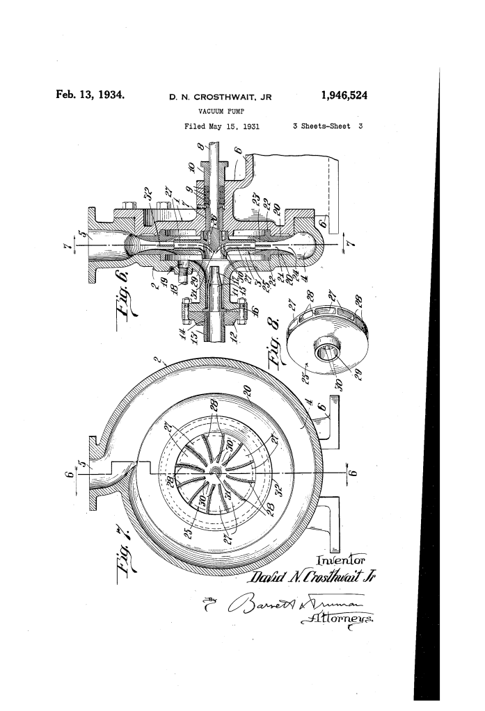
Dual-Chamber Integration
- Single Shaft Logic: One version of the pump places a centrifugal supply pump and the vacuum exhauster on the same shaft, powered by one motor. The first stage creates the pressure, and the second stage uses that pressure to create the vacuum.
Comparison: Standard Jet Exhausters vs. The Crosthwait Pump
| Feature | Standard Jet Exhauster | Crosthwait Vacuum Pump |
| Mechanism | Static nozzle only | Rotary impeller + high-velocity jet |
| Liquid State | Solid stream | Dispersed “atomized” particles |
| Energy Source | Fluid pressure only | Fluid pressure + Centrifugal force |
| Reliability | Prone to losing prime | Self-priming via internal channels |
Significance
- Modern Centrifugal Exhausters: This design is a direct ancestor to the high-efficiency vacuum systems used today in industrial chemical processing and laboratory environments.
- HVAC Efficiency: By creating a more powerful vacuum with a smaller footprint, Crosthwait allowed large buildings to use “sub-atmospheric” steam, which travels faster and heats more evenly.
- Mechanical Reliability: The “packingless” design (operating under vacuum rather than high pressure at the shaft) reduced wear and tear, a major step forward in industrial durability.
