
Triggered Exploding Wire Device (1966)
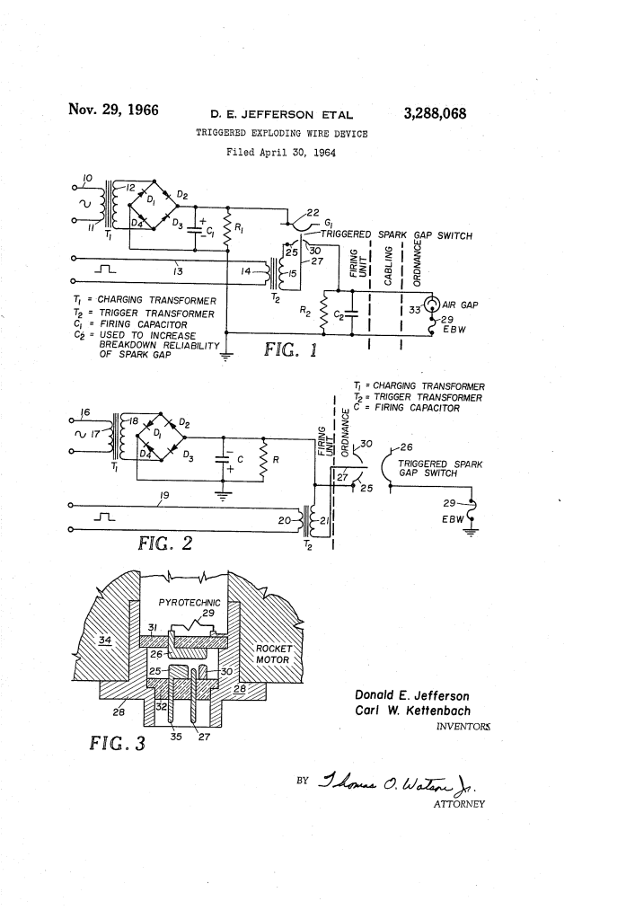
U.S. Patent No. 3,288,068, granted on November 29, 1966, to Donald E. Jefferson and Carl W. Kettenbach, addresses a vital safety and reliability dilemma in military and aerospace ordnance: how to trigger exploding bridge wire (EBW) detonation systems without the risk of accidental initiation caused by stray voltages, radio interference, or electromagnetic pulses.
Assigned to the United States of America as represented by the Secretary of the Navy, this invention introduced an integrated, highly ruggedized electro-explosive initiator that consolidated the firing trigger and the explosive bridge wire into a single plug-in component, eliminating bulky auxiliary circuits and failure-prone cabling.
The Innovation: The Integrated Spark Gap-Bridge Wire Unit
Exploding bridge wire systems are critical in missile stage separation, rocket motor ignition, gas generator activation, and emergency vehicle destruction. Unlike standard blasting caps, EBWs do not use sensitive primary explosives; they require a massive, instantaneous surge of electrical current to vaporize a fine wire and create a high-energy detonation wave.
Prior firing systems used a standalone triggered spark gap switch in an external firing unit, connected through a long transmission cable to an isolated air gap (33) and the bridge wire inside the ordnance. This legacy approach suffered from severe drawbacks:
- Critical Circuit Balancing: It required a secondary parallel RC network (R2, C2) across the line to force breakdown across the remote air gap, making system timing hypersensitive to component variations.
- Vulnerability to Stray Signals: The external protective air gap shielded the wire only against inadvertent DC potentials up to roughly 500 volts and AC signals up to 120 volts.
- Cable Losses and Inductance: Running high-voltage trigger pulses through long transmission lines introduced parasitic inductance, pulse degradation, and electromagnetic pick-up.
Jefferson and Kettenbach resolved these vulnerabilities by integrating the triggered spark gap directly into the ordnance casing alongside the bridge wire, connecting the exploding wire directly between the switch anode and the grounded metallic shell.
Why the Integral Gap Architecture?
- Higher Voltage Immunity: Moving the spark gap directly into a sealed gas chamber increased the baseline breakdown threshold, providing far superior immunity against high-level accidental AC and DC voltages.
- Elimination of Auxiliary Circuits: It completely removed the need for the secondary parallel RC network (R2, C2) and the external protective air gap (33).
- Direct Plug-In Connection: Combining the trigger probe, annular cathode, and bridge wire within an all-in-one housing allowed the firing unit to mount directly on top of the rocket motor or ordnance casing, eliminating long transmission cables entirely.
How the Apparatus Functions
The firing process follows a coordinated electrical sequence requiring simultaneous multi-terminal inputs to initiate detonation:
| Step | Action | Safety & Operational Purpose |
| 1. High-Voltage Arming | The main firing capacitor (C1) charges via transformer T1 and applies a high DC potential between cathode (25) and ground casing (28). | Stores the high-energy surge needed to vaporize the bridge wire while remaining safely decoupled from the explosive. |
| 2. Trigger Pulse Ingestion | A sharp trigger pulse is delivered to the input of trigger transformer T2. | Provides the secondary firing command; without this simultaneous pulse, the switch remains non-conductive. |
| 3. Gas Ionization | Transformer T2 steps up the pulse between trigger probe (27) and annular cathode (25, 30). | Ionizes the gas inside the sealed chamber, collapsing dielectric resistance between cathode and anode. |
| 4. Main Gap Discharge | Electrostatic breakdown occurs across the main gap from cathode (25) to anode (26). | Dumps the stored energy from capacitor C1 directly across the anode terminal with negligible line loss. |
| 5. Bridge Wire Vaporization | Surge current flows through exploding bridge wire (EBW) to grounded casing (28). | The wire instantly vaporizes, detonating the adjacent pyrotechnic charge to initiate rocket staging or destruction. |
Technical Components
The self-contained ordnance package combines electrical switching with mechanical containment:
- Conductive Outer Casing (28): A cylindrical metallic shell that encloses the assembly, provides structural mounting directly to the rocket motor, and serves as common electrical ground for the firing circuit.
- Ceramic Insulating Supports (31, 32): Heavy-duty ceramic partition walls extending between the inner casing walls, hermetically sealing a central gas-filled chamber. They are structurally reinforced (or built with metal-to-ceramic feedthroughs) to prevent pyrotechnic blowback into the firing circuit during detonation.
- Ionizable Gas Chamber: The hermetically sealed interior space enclosed by the ceramic walls, containing a calibrated gas mixture that breaks down rapidly under probe excitation.
- Annular Cathode (25, 30) & Pin (35): A ring-shaped cathode positioned inside the gas chamber with an integral pin (35) extending through ceramic wall 32 to form an external plug-in terminal.
- Centered Trigger Probe (27): A conductive electrode projecting through support 32 into the center opening of the cathode ring, maintaining a precise spark gap spacing for reliable ionization.
- Anode Electrode (26): Mounted on opposing support 31, projecting through the insulator to connect directly to the bridge wire.
- Exploding Bridge Wire (EBW): A precision micro-wire positioned in the pyrotechnic compartment, welded directly between the projecting tip of anode 26 and the grounded outer casing 28.
Historical and Scientific Impact
Developed during the mid-1960s expansion of the U.S. naval and aerospace missile arsenals, the Jefferson-Kettenbach initiator significantly elevated the safety standards of solid-propellant rocketry:
- Inherent Logistics Safety: Because the device paired insensitive secondary pyrotechnics with high breakdown gap voltages, entire missiles and payloads could be transported, handled, and staged in high-RF environments (such as aircraft carrier flight decks) without needing mechanical out-of-line safing pins.
- Aerospace Miniaturization: By replacing separate firing units, junction boxes, high-voltage coaxial cables, and intermediate spark gaps with a single compact plug-in component, the design reduced dead weight on missile airframes.
- Foundation for Modern Slapper Detonators: The structural concepts pioneered in this patent—close-coupling high-voltage discharge capacitors and spark switches directly to the exploding initiator—laid the technical foundation for subsequent exploding foil initiators (EFIs) and modern high-precision aerospace safety-and-arming (S&A) modules.
About the Inventors
Donald E. Jefferson and Carl W. Kettenbach were research engineers at the Naval Ordnance Laboratory (NOL) in White Oak, Maryland, a premier military research facility responsible for foundational advancements in naval weapons, explosives, fuzing, and missile guidance.
During their careers at NOL and related defense establishments, Jefferson and Kettenbach focused on high-speed electrical discharge phenomena, pulsed-power switching, and ordnance safety engineering. Their specialized work on exploding bridge wire mechanics helped ensure that America’s missile systems and satellite deployment stages functioned with microsecond precision while maintaining absolute safety against inadvertent static or electrical ignition.
Summary of Claims
The patent explicitly claims:
- An electro-explosive firing system comprising an anode, cathode, and trigger probe spark gap housed within a conductive casing and isolated by insulating ceramic supports enclosing a gas-filled space.
- An exploding bridge wire connected directly between the conductive casing and the anode in close physical proximity to the switch.
- An annular cathode design featuring a center opening that receives the trigger probe to initiate gas ionization.
- A unitary ordnance device combining the spark gap and the exploding bridge wire into a single plug-in package that eliminates intermediate transmission cabling between the switch and the pyrotechnic charge.
