
Transistorized Multivibrator Circuit (1961)
U.S. Patent No. 3,005,953, granted on October 24, 1961, to Philip Emile, Jr., introduces a specialized transistorized circuit designed for high-speed computing and timing. Unlike a standard free-running multivibrator that oscillates indefinitely, this circuit is engineered to produce a specific, predetermined number of pulses in response to a single trigger signal before automatically shutting itself off.
The Problem: Complexity in Pulse Multiplication
In early computer circuitry, generating a burst of pulses (e.g., for a “clock” or a multiplication step) usually required complex counting hardware or stable delay lines. Emile sought to achieve this using a simple, compact circuit that exploited the physical characteristics of transistors.
The Innovation: The “Lost Charge” Effect
The invention relies on a phenomenon inherent in saturated transistors: Storage Time. To turn off a transistor that is in a state of “saturation” (fully on), a specific amount of electrical charge must first be removed from its base.
Emile’s circuit is designed to “accentuate” this effect. By choosing specific values for the coupling capacitors and resistors, each oscillation cycle slightly depletes the available charge on the capacitors. This creates a cumulative decay in the oscillation time.
Shutterstock
How the Circuit Works
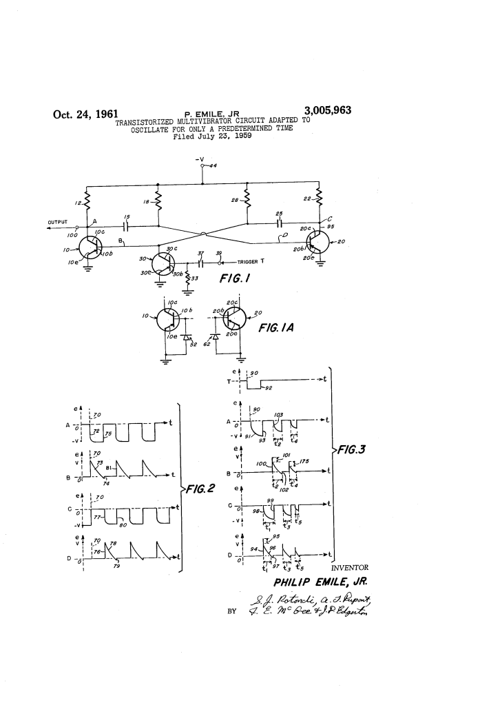
The circuit consists of two main transistors (10 and 20) in a cross-coupled configuration, plus a third transistor (30) used as a trigger.
- Initial State: Before a trigger pulse arrives, both transistors are in a “saturated” (conductive) state. No oscillation occurs.
- Triggering: A pulse is applied to transistor 30, which momentarily cuts off transistor 10. This “kicks” the multivibrator into action.
- Cumulative Oscillation: The circuit begins to oscillate like a normal free-running multivibrator. However, because the capacitors are small, the “lost charge” required to flip the transistors back and forth causes the voltage on the capacitors to drop significantly with every cycle.
- Sharp Cutoff: As the cycles progress (t_1, t_2, t_3), the timing intervals get shorter and shorter. Eventually, the charge on the capacitors becomes too low to trigger the next flip. The oscillations stop abruptly, and the circuit returns to its resting saturated state.
Performance and Stability
The patent highlights that this method produces a “sharp” stop rather than a gradual, unpredictable fading. This makes the pulse count highly reliable:
- Small Pulse Counts: Extremely stable for counts under 10.
- Large Pulse Counts: Very stable for counts up to 25.
- Variable Timing: By adjusting the components, the circuit can be tuned to oscillate for as little as a few microseconds or as long as 10 minutes.
Technical Specifications (Example)
In one specific embodiment (FIG 1A), the circuit used the following parameters to consistently generate 17 pulses per trigger:
| Component | Value |
| Transistors (10, 20, 30) | Type 2N207 (PNP) |
| Coupling Capacitors | 1,000 micromicrofarads (pF) |
| Base Resistors | 51,000 Omega |
| Collector Resistors | 12,000 Omega |
| Supply Voltage (V) | 10V(Stable from 5V to 15V) |
Applications
- Computers: Used as a pulse multiplier to generate a specific burst of clock cycles.
- Electronic Timing: Serving as a compact substitute for bulky time-delay relays or complex gas-discharge tube circuits.
- Signal Processing: Generating a fixed-length pulse train for communication systems.
