
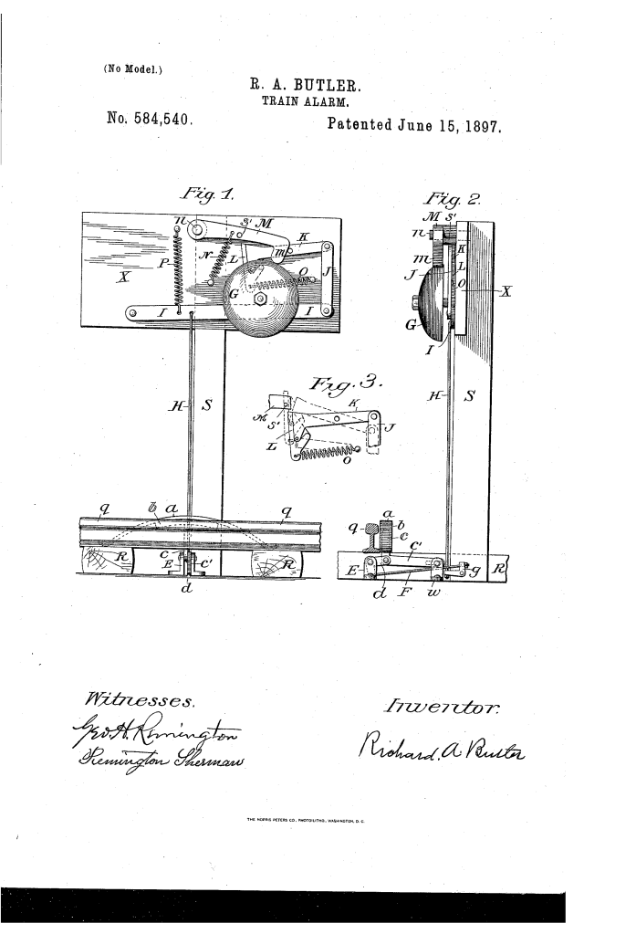
Train Alarm (1897)
U.S. Patent No. 584,540, granted on June 15, 1897, to Richard A. Butler, describes a mechanical track-side warning system designed to protect railroad brakemen and crew members from low-clearance hazards, particularly overhead bridges.
During the late 19th century, trainmen frequently had to walk atop moving freight cars to operate manual hand brakes. Low-clearance bridges presented a constant, often fatal hazard. Butler, an inventor based in Pawtucket, Rhode Island, devised an automated, track-actuated alarm system that mechanically sounded a loud gong positioned at roof-level just as a train approached an overhead obstruction.
The Core Design: The Track-to-Gong Linkage
The primary innovation of Butler’s system lies in its purely mechanical, dependable linkage that transfers the immense downward force of a train’s wheels into a rapid, spring-loaded hammer strike against an elevated warning bell.
1. The Trackside Plunger and Spring-Shoe (a, b, c)
- A curved strip of spring-steel (a) is mounted on a metal cushion (b) and supported by a vertical plunger (c).
- The ends of the spring rest near the rail or ties, arched so that the top rises slightly above the railhead on the outside track.
- As the heavy wheels of an oncoming train roll over the rail, the wheel tread depresses the spring-shoe, driving the plunger (c) downward.
2. The Ground-Level Bell-Crank Transfer (d, E, e, F)
- The plunger connects directly to a bell-crank lever (d) fulcrumed on a double post (E).
- An extending arm (e) slides within a slotted axis on a second post (10) to guide and limit the stroke.
- Downward motion is translated horizontally through a tension wire (F), safely housed within a protective ground casing running perpendicular to the tracks.
How the Alarm Functions
The mechanism operates through an immediate, sequential chain reaction across mechanical linkages to strike the roof-level gong:
| Step | Action | Mechanical Purpose |
| 1. Actuation | The train wheel rolls over the spring (a), depressing the plunger (c). | Captures mechanical force directly from the moving train. |
| 2. Base Transfer | Plunger moves bell-crank lever (d), pulling wire (F) to the base of post (S). | Transmits force laterally from the track bed to the alarm post. |
| 3. Vertical Lift | Wire (F) trips elbow lever (g), pulling vertical wire/rod (H) upward along post guides. | Directs the kinetic stroke up to the roof-level frame (X). |
| 4. Hammer Cocking | Linkage arms (I, J, K) raise trip-toe (L), catching shaft (s) on hammer arm (M). | Cocks hammer (m) back against the resistance of heavy spiral spring (N). |
| 5. Strike & Reset | Trip-toe (L) slips past shaft (s); spring (N) drives hammer (m) into gong (G). Springs (p, o) reset the linkage. | Produces a loud auditory alert at freight-car roof level, immediately resetting for the next wheel. |
Key Mechanical Components
- Spring-Steel Shoe (a): Rises above the rail outside the wheel guide to reliably catch wheel treads without derailing or binding.
- Overhead Frame (X) & Gong (G): Elevated on post (S) specifically to the height of a freight-car roof, delivering the warning directly into the ear line of trainmen on top of the cars.
- Trip-Toe Mechanism (L, s): A pivoting release latch that lifts the hammer shaft and abruptly slips free, allowing the hammer (m) to snap forward forcefully under full spring tension.
- Spiral Springs (N, o, p): Dedicated return springs that ensure high impact velocity on the bell strike and instant mechanical reset between passing wheel sets.
Historical and Practical Impact
In an era before standardized electronic track circuits and cab signaling, overhead bridge collisions were among the leading causes of injury and death for railroad workers.
- Targeted Roof-Level Protection: By elevating the gong to the exact height of the freight cars, the sound was not muffled by wheel noise or track vibrations, cutting straight through wind and steam to alert crew members atop the train.
- Mechanical Certainty: The design bypassed fragile batteries or electrical lines of the era, relying entirely on the weight of the train itself for power.
- Durability: The spring cushion (b) and reciprocating arm (e) absorbed the severe shock of high-tonnage wheel strikes, preventing the linkage from snapping under high-speed operation.
About the Inventor: Richard A. Butler
Richard A. Butler of Pawtucket, Rhode Island, focused his inventive efforts on vital practical improvements in railway infrastructure and worker safety. Operating during the height of the American industrial railroad expansion in the late 19th century, Butler identified severe operational hazards and engineered simple, robust mechanical systems to safeguard railroad personnel.
Summary of Claims
The patent explicitly claims:
- The combination of a spring-shoe extending above the rail, an elevated alarm-gong post, an operative mechanical connection from the plunger to the gong, and a reciprocating guide rod (e) configured to limit operating stroke.
- The specific mechanical train comprising the curved track spring (a), cushion (b), plunger (c), bell-crank levers (d, g), intermediate transmission wires (F, H), articulated linkage arms (I, J, K), spring-loaded trip-toe (L), hammer trip shaft (s), heavy strike spring (N), and elevated gong (G).
