
Time Control System for Telephones, Charles V. Richey, Patent No. 1,897,533
The patent by Charles V. Richey of Jamaica, New York describes a Time Control System for Telephones (Patent No. 1,897,533). This invention is an electromechanical duration-metering switch integrated into the talking circuit of long-distance or public pay-station telephones. It is designed to automatically monitor a paid conversation period, provide a momentary warning signal as the time expires, and then forcibly disconnect the transmission unless the operator resets the timer for a newly paid interval.
The “Why”
In the 1930s, telephone companies suffered significant financial losses from “over-talking” in public booths. Callers would often exceed their paid time and leave the booth without paying the overtime toll. A common tactic was leaving the receiver off the hook, preventing the operator from signaling the local store clerk to collect the fee. Richey’s invention addressed this revenue leakage by moving control from the user’s honesty to a hard mechanical cutoff. It provided a professional way to remind callers to “deposit another coin” without a jarring, immediate disconnection.
Inventor Section: Charles V. Richey
Charles Richey, an assignor to American Telephone and Telegraph (AT&T), operated within the peak of the Bell System’s infrastructure expansion. His engineering philosophy was centered on automated enforcement and signaling. Richey recognized that the telephone operator—already busy managing multiple lines—needed a mechanical assistant to handle the “policing” of toll calls. His device acted as a bridge between continuous clockwork and variable human interaction, ensuring the company was compensated for every minute of line usage.
Key Systems Section
1. Clockwork Drive and Friction Coupling
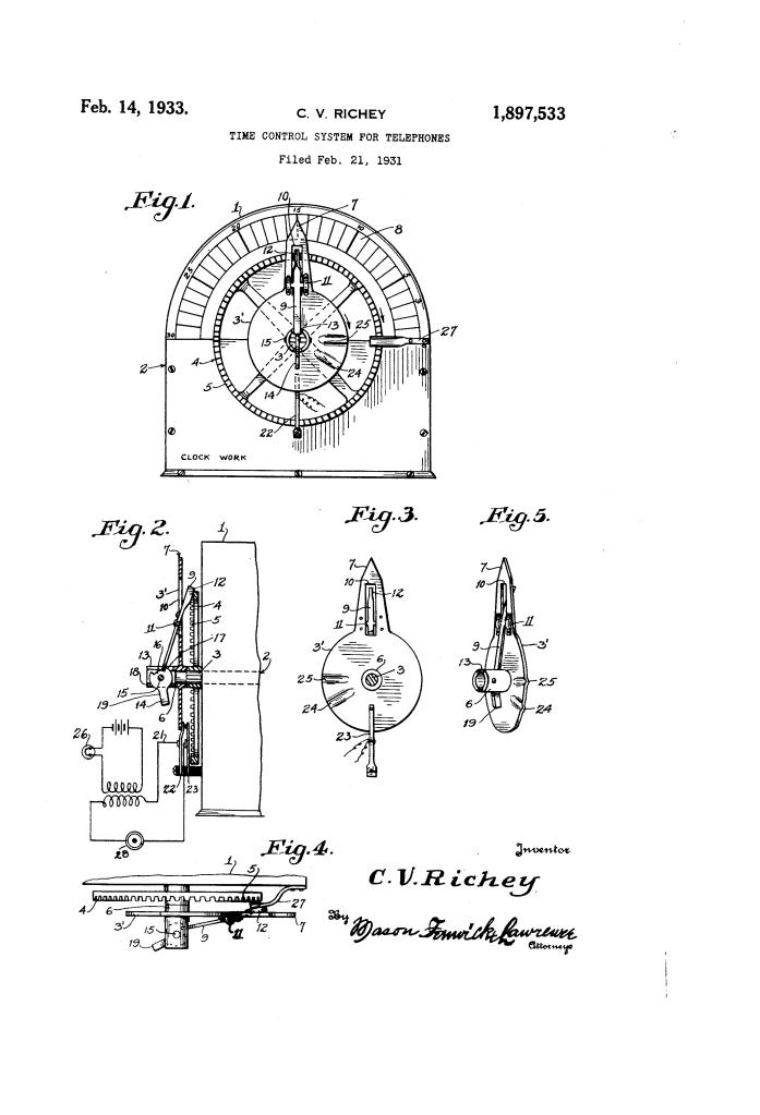
The device is powered by a continuous clockwork (2) that rotates a main shaft (3) and a gear wheel (4) at a constant speed.
- Modern Engineering Term: Synchronous timing drive.
- The operator sets the time by manually rotating a disk (3′) against the shaft’s friction. To “start” the timer, the operator uses a handle (19) to engage a pawl (9) with the gear teeth (5). This latches the disk to the clock, beginning a timed return to the “zero” position.
2. The Sequential Cam-Switch Interface
The disk (3′) acts as a physical cam that controls the talking circuit switch (20).
- Modern Engineering Term: Programmed cam-actuated switch.
- The switch consists of two spring contacts (22, 23). While the call is active, the smooth edge of the disk holds the contacts together.
- Warning Phase: Near the end of the rotation, a small depression (24) allows contact 22 to momentarily drop, opening the circuit briefly and causing the operator’s light to flicker.
- Cutoff Phase: When time officially expires, a deeper depression (25) allows the contacts to open permanently, killing the transmission.
3. Visual Index and Operator Interface
To ensure accuracy, the device features an arcuate scale (8) divided into minute and five-minute intervals.
- Modern Engineering Term: Analog user interface (UI).
- This allows the operator to precisely “program” the call duration. Because the disk is friction-mounted, the operator can reset the conversation for another period without the caller ever knowing a mechanical switch was involved, provided the second payment is made before the “cutoff” depression is reached.
4. Automatic Pawl Release
To prevent the clockwork from binding once the timer reaches zero, a lifting spring (27) is positioned at the return limit.
- Modern Engineering Term: End-of-travel limit release.
- As the disk reaches its final position, the spring catches the pawl (9) and lifts it out of the gear teeth, effectively “declutching” the timer and allowing the clockwork to continue rotating freely for other units on the same master shaft.
Comparison: Manual Monitoring vs. Richey’s Time Control
| Feature | Standard Manual Operation (1931) | Richey’s Timing System |
| Duration Tracking | Operator’s memory or stopwatch. | Automated clockwork countdown. |
| Call Termination | Operator must manually pull a plug. | Automatic circuit break via cam depression. |
| Warning Signal | Operator interrupts to speak. | Momentary flicker in line and signal light. |
| Revenue Protection | High risk of unpaid overtime. | Forced cutoff ensures payment for all time used. |
Significance
- Precursor to Digital Billing: Richey’s system is a direct ancestor to the automated billing software used by modern telecom carriers to track data and minutes.
- Automated Customer UX: The “warning flicker” was an early implementation of a system notification, allowing users to react before a hard system failure (disconnection).
- Network Scalability: By allowing a single master clock to drive multiple switch mechanisms, Richey enabled a single exchange to handle dozens of metered public booths simultaneously with minimal extra labor.
