
Tie Plate and Joint Brace (Ned E. Barnes, No. 1,655,305)
The patent by Ned E. Barnes of Willis, Texas, describes an improved Tie Plate and Joint Brace (Patent No. 1,655,305, 1928). This invention is a heavy-duty railway safety component designed to reinforce the “joint”—the point where two rail ends meet—on a railroad track. Barnes’s primary objective was to prevent the rails from sinking or spreading at their weakest point and to ensure that the abutting rail ends remained in perfect alignment. His innovation integrates a traditional tie plate with a structural wing plate and a specialized support leg, creating a unified brace that spans multiple ties.
Inventor Background: Ned E. Barnes
Ned E. Barnes was an African American inventor based in Texas during the late 1920s. His work addressed one of the most persistent engineering challenges of the railroad era: joint maintenance. On early 20th-century railroads, the constant pounding of heavy locomotives often caused rail ends to dip or spread, leading to derailments. Barnes’s patent demonstrates a sophisticated understanding of load distribution and structural geometry, providing a solution that was both “simple in structure” and “cheaply produced,” making it a practical improvement for the rapidly expanding rail networks of the Southern United States.
Key Mechanical & Structural Systems
The brace is a multi-part assembly that clamps the rail ends into a rigid, non-slip position.
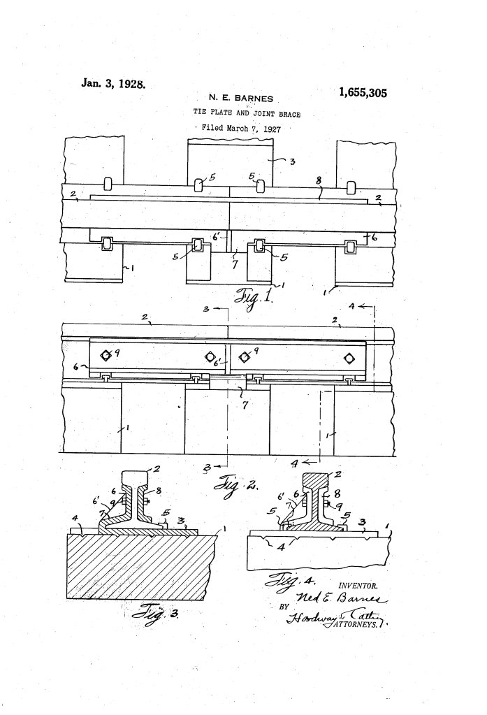
1. The Toothed Base Plate (3, 4)
- Design: An elongated base plate (3) rests on the railway tie (1) directly beneath the rail joint.
- Anti-Slippage: The underside of the plate is equipped with teeth (4).
- Function: These teeth “bite” into the wooden tie when the weight of the train passes over. This prevents the plate from sliding laterally, ensuring the track gauge (width) remains constant.
2. The Integrated Wing Plate and Central Leg (6, 7) (Key Innovation)
- Wing Plate (6): A structural member that conforms to the outer contour of the rail web (the vertical part of the rail).
- Central Leg (7): This leg is formed integrally with the base plate and wing plate, fitting tightly over the base of the rail.
- Function: By “bridging” or “breaking” the joint between the two rail ends, the wing plate acts as a rigid splint. The integral leg (7) provides a massive amount of vertical and horizontal stability that a standard separate plate could not achieve.
3. The Fish Plate and Clamping System (8, 9)
- Fish Plate (8): A matching plate is fitted against the inside of the rail, opposite the wing plate.
- Clamp Bolts (9): Both the wing plate and the fish plate are secured to the rail web using heavy bolts (9).
- Function: This creates a “sandwich” effect, clamping the two rail ends together so they move as a single unit, preventing one end from sinking lower than the other when a wheel passes over the gap.
4. The Triple-Tie Support Span
- Extended Length: Both the wing plate (6) and the fish plate (8) are significantly longer than standard plates.
- Function: They are designed to overlap not only the tie directly under the joint but also the adjacent ties on each side. This “triple-tie” span distributes the impact of the train over a larger surface area, preventing the rails from sinking into the ballast.
Improvements Over Standard Railway Braces
| Feature | Standard Joint Bars / Plates | Barnes’s Tie Plate & Joint Brace |
| Sinking Prevention | Only supported by the single tie under the joint. | Triple-tie span distributes weight over three ties. |
| Rail Spreading | Relied solely on spikes to prevent width change. | Toothed base (4) and integral wing plate lock the gauge. |
| Alignment | Rails could “offset” horizontally or vertically. | Conforming wing plate (6) holds the web in perfect alignment. |
| Durability | Joint components often rattled loose. | Integral leg (7) and reinforced web (6′) provide maximum rigidity. |
Significance to Civil and Railroad Engineering
Ned E. Barnes’s tie plate and brace influenced the development of track stability systems and heavy-load distribution logic.
- Integral Casting: Barnes’s decision to make the wing plate and base plate a single integral unit anticipated the move toward monoblock track components that reduce the number of individual parts prone to vibrating loose.
- Bridge Engineering on a Small Scale: Treating a rail joint as a “bridge” over multiple supports (ties) is a foundational principle in structural load management, ensuring that local stress does not lead to systemic failure.
- Gauge Maintenance: His use of “biting teeth” is a mechanical logic still found in modern serrated tie plates used on high-curvature tracks where lateral forces are extreme.
- Safety Redundancy: By providing both vertical support (the base plate) and lateral reinforcement (the wing/fish plates) in a single system, Barnes enhanced the factor of safety for high-speed rail travel.
