
Therapeutic Carbon Arc Lamp (Paul E. Johnson, No. 1,842,100)
This 1932 patent by Paul E. Johnson of Chicago represents an advancement in early 20th-century “light therapy.” During this era, carbon arc lamps were used to simulate sunlight (UV and infrared rays) to treat various skin conditions, respiratory ailments, and vitamin D deficiencies. Johnson’s design addressed the major flaws of previous models: they were typically massive, expensive, and required specialized high-voltage wiring.
1. The Carbon Arc Mechanism
The “sunlight equivalent” is generated by creating an electrical arc between two carbon rods (electrodes).
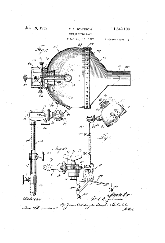
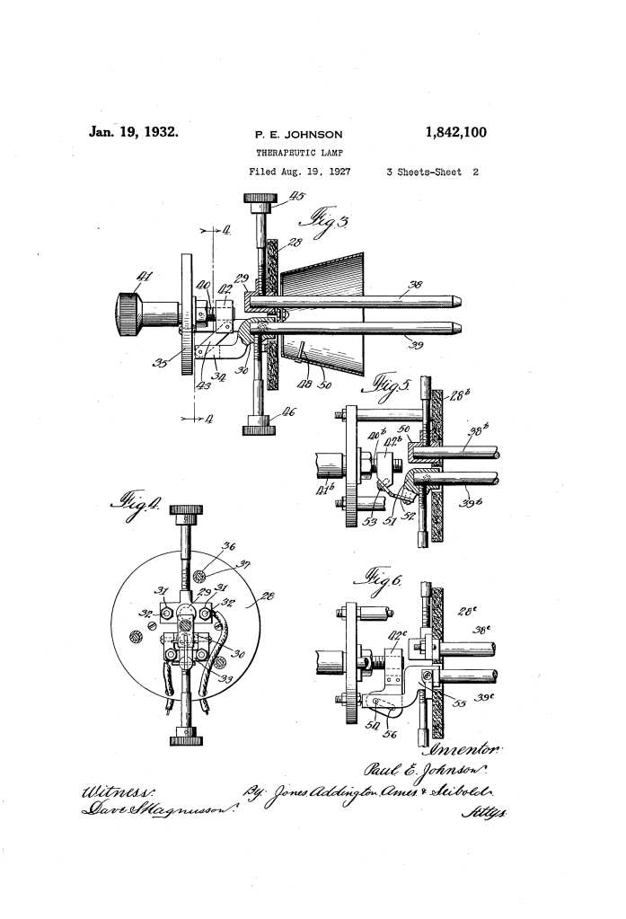
- Arc Initiation: The operator uses a handle (41) to bring the carbon electrodes (38, 39) together to touch, then slowly separates them. This creates a high-intensity bridge of light (the arc).
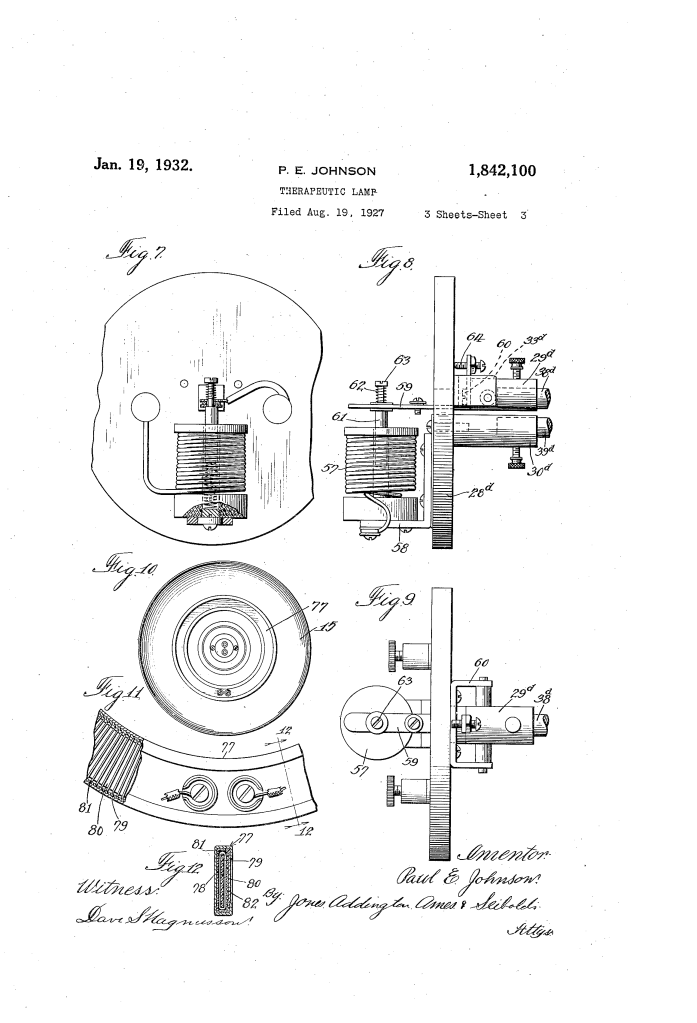
- Mechanical Control: Because carbons burn away during use, the lamp includes a precision screw mechanism to adjust the gap. In some embodiments, Johnson used a solenoid (57) to automatically maintain the arc distance via electromagnetic pull.
- Insulation and Cooling: To protect the delicate adjustment gears from the intense heat of the arc, they are mounted behind a heat insulating plate (28) (made of asbestos or porcelain) and enclosed in a perforated casing (44) to allow for air cooling.
2. Therapeutic Enhancements: The Dual-Ray System
Unlike standard lighting, this lamp was designed to maximize specific therapeutic wavelengths.
- The Resistance Element (77): In a standard setup, a resistor is used to step down the current. Johnson moved this resistor from the base of the lamp into the reflecting chamber (15) itself.
- Infrared Generation: By placing the resistance wire inside the lamp head, the “wasted” heat is converted into infrared rays. This allows the patient to receive both the ultraviolet light from the carbon arc and the deep-penetrating heat from the resistor simultaneously.
- Safety Filters: A screen (24) or quartz glass covers the opening to prevent hot sparks from the carbons from falling onto the patient. Localizers (26) can be attached to focus the light into specific areas like the nose or throat.
3. Ergonomics and Mobility
The lamp was designed for ease of use in a clinical or home setting.
- Telescoping Mast (16): The lamp is mounted on a series of nested pipes, allowing for height adjustment.
- Universal Joint: A bracket and handle system (65, 66, 67) allows the reflecting chamber to be tilted or rotated to any angle.
- Spider Base (17): The heavy base is mounted on casters, providing stability while allowing the unit to be rolled between treatment rooms.
4. Technical Summary of Components
| Component | Function |
| Carbon Electrodes | Generate UV and visible light via electrical arcing. |
| Reflecting Chamber | Focuses rays toward the patient; lined with inner reflectors. |
| Observation Windows | Colored glass ports that allow the operator to check the arc without eye damage. |
| Kelvin/Main Switch | Integrated into the pivot point to minimize messy wiring. |
Historical and Medical Context
In the 1920s and 30s, “heliotherapy” (sun therapy) was a mainstream medical practice. Johnson’s lamp was marketed as a way to bring the benefits of the sun indoors. While we now know the risks of unregulated UV exposure, these devices were the direct ancestors of modern phototherapy units used today for conditions like neonatal jaundice and psoriasis.
