
Theft-Preventing Device for Vehicles (J. A. Johnson & J. P. Thompson, No. 1,443,450)
The patent by John Arthur Johnson and James Pearl Thompson of Leavenworth, Kansas, describes a Theft-Preventing Device for Vehicles (Patent No. 1,443,450, 1922). This invention is a specialized locking mechanism integrated directly into the fuel intake system of internal combustion engines. The inventors’ primary objective was to provide a reliable way to shut off the fuel supply, thereby preventing unauthorized operation of automobiles, trucks, tractors, or aircraft.
Inventor Background: Johnson & Thompson
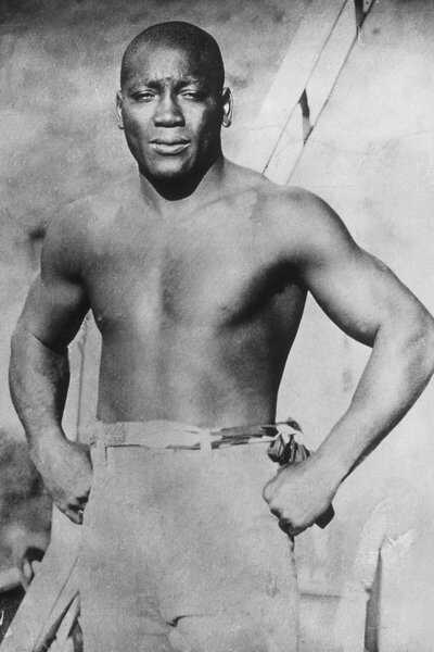
John Arthur Johnson was a prolific African American inventor (also known for his 1922 wrench patent) who collaborated with James Pearl Thompson on this security device. During the early 1920s, as vehicle ownership spiked, so did automobile theft. Their invention addressed the vulnerability of early ignition systems by moving the security “barrier” from the electrical system to the physical fuel line, making the vehicle nearly impossible to start even if the ignition was bypassed.
Key Mechanical & Security Systems
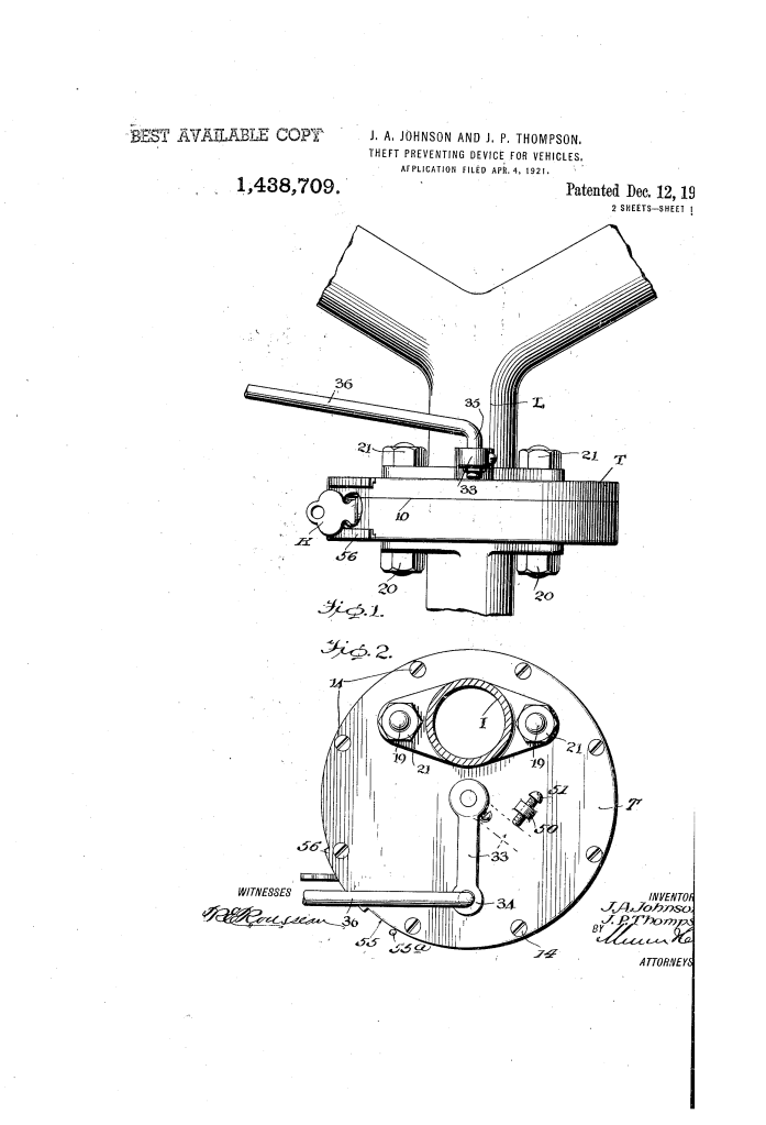
The device is a “valve-in-casing” system installed between the carburetor and the intake manifold.
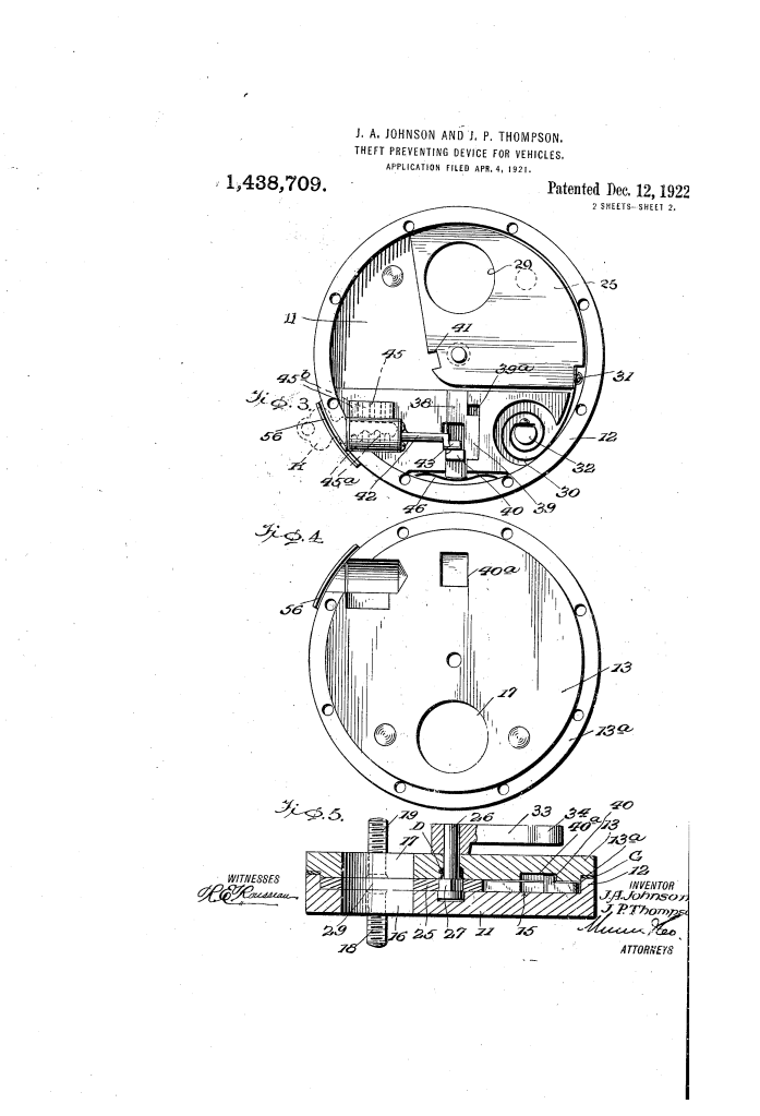
1. The Swinging Sector Valve (25)
- Structure: A flat, sector-shaped valve (25) mounted on a rotatable shaft (26).
- Dual-Function Surface:
- Opening (29): One side of the valve has a circular hole. When aligned with the manifold openings (16, 17), fuel flows freely.
- Imperforate Portion: The rest of the valve is solid. When swung into place, it completely obstructs the fuel passage.
- Automatic Reset: A coil spring (30) is attached to a stationary post (32), normally holding the valve in the “open” position for driving.
2. The Locking Mechanism (38, 41, 42)
- The Bolt (38): A spring-loaded locking bolt is housed within the casing.
- The Keeper (41): The valve itself contains a notch or “keeper.” When the valve is manually closed from the dash, the bolt (38) snaps into the keeper (41).
- Key Control: To unlock the fuel line, the owner must use a key in the lock cylinder (42). Turning the key rotates a shaft that retracts the bolt, allowing the main spring (30) to snap the valve back to the “open” position.
3. The Adjustable Throttle/Abutment (50, 51)
- Bumping Post (50): An external post on the casing supports a set screw (51).
- Function: This act as an adjustable stop for the crank arm (33). By adjusting this screw, the owner can use the device as a secondary throttle to limit maximum fuel flow, or set it so the valve cannot be fully closed without manual override.
Engineering Features and Safety Logic
| Feature | Hazard Addressed | Engineering Solution |
| Direct Manifold Integration | Bypassing ignition (hotwiring). | Cuts off the actual “food” (fuel) of the engine; no fuel means no combustion. |
| Spring-Loaded Bolt (46) | Vibration unlocking the valve. | Ensures the bolt stays firmly seated in the keeper until manually retracted by a key. |
| Squared Shaft (27) | Mechanical slippage. | The valve and shaft use a squared connection to prevent the valve from spinning loosely under pressure. |
| Dust Cover (52) | Lock jamming. | A swinging plate protects the keyhole from road dust and debris. |
Significance to Automotive Engineering
The Johnson-Thompson device was a sophisticated precursor to modern vehicle immobilizers.
- Physical Immobilization: Unlike modern electronic chips, this was a “hard” security feature. Even if a thief replaced the entire ignition, they could not move the car without dismantling the fuel intake—a loud and time-consuming process.
- Universal Application: The design was modular, intended for use on everything from tractors to aeroplanes, highlighting the inventors’ vision for a broad security standard across the transport industry.
- Multi-Use Utility: By allowing the device to function as both a lock and a throttle, they added value to the mechanism, making it a functional part of engine performance management as well as security.
