
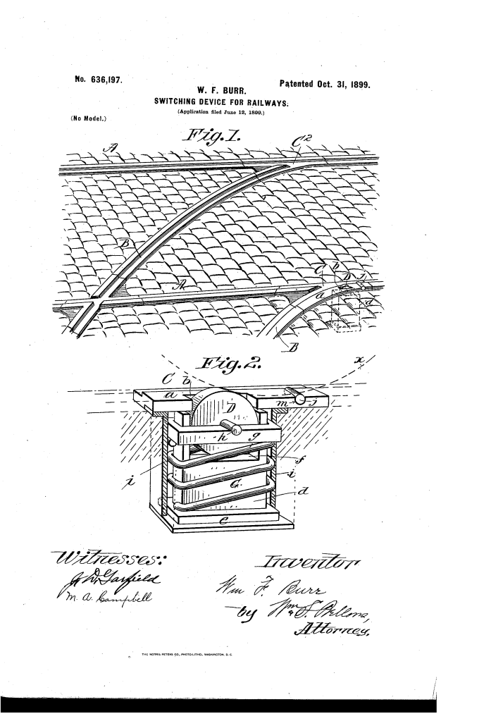
Switching Device for Railways (1899)
U.S. Patent No. 636,197, granted on October 31, 1899, to William F. Burr, introduces an automatic track-switching mechanism designed for street railways. William F. Burr, an inventor residing in Agawam, Massachusetts (who assigned half of his patent rights to Oscar L. King), developed a passive, mechanical track system capable of directing streetcars without requiring electrical overhead switch actuators, manual track levers, or track attendants.
The invention resolved a common operational challenge on urban transit lines: how to reliably divert a streetcar onto a siding or branch line—or maintain its route along the straight main track—governed solely by the operating speed chosen by the motorman as the car approaches the junction.
The Innovation: The Velocity-Controlled Dual-Roller Mechanism
Conventional street railway switches of the era often relied on manual switch points, mechanical linkages operated from the car platform, or track attendants stationed at busy intersections. Burr’s breakthrough was an automatic, momentum-governed switch bed embedded directly into the track frog.
By placing a dual-roller assembly in the tread portion of the rail, the switch acts on the car wheel’s traction. At slow speeds, the car’s leading wheel loses forward traction and idles over the rollers, creating a brief pivot point that swings the car’s opposing wheel into the siding track. At normal or higher speeds, the momentum carries the wheel directly across the switch plate before any idling or pivoting can take place.
Key Mechanical Assemblies
The switching mechanism integrates directly into the junction frog plate using several interconnected components:
- The Spring-Loaded Primary Roller (D)Mounted within an aperture (b) in the rail tread, its upper periphery protrudes slightly above the rail head. It rests on a vertically movable journal yoke (g) supported by a stiff helical spring (G) that yields downward under the full deadweight of the streetcar wheel.
- The Fixed Auxiliary Roller (j)Positioned rearward of the primary roller, this smaller roll is set into a dedicated socket seat (m) that wraps around more than half of its circumference, locking it in place against displacement while allowing free rotation.
- Housing and Foundation AssemblyA standard upright (d) rises from a base (e) mounted on cross-ties beneath the pavement level. A protective casing (i) completely encloses the spring, journal yoke, and the lower half of the roller assembly to block street grit, dirt, and moisture.
Technical Components
| Component | Function |
| Primary Roller (D) | Large spring-supported roll that temporarily eliminates wheel traction and compresses downward under full car weight. |
| Auxiliary Roller (j) | Compact roll set in socket seat m to provide a secondary idling contact point for the wheel rim. |
| Yoke / Journal Frame (g) | Recessed guide frame holding the arbor of roller D, allowing smooth vertical travel. |
| Supporting Spring (G) | Stiff compression spring that keeps roller D elevated until overcome by car weight. |
| Standard Upright (d) & Base (e) | Foundation structure anchored beneath the roadbed to support the moving parts. |
| Protective Casing (i) | Environmental housing shielding the spring and bearing assemblies from dirt, water, and debris. |
| Frog Plate (C, C) | Track junction casting containing aperture b and socket seat m within rail tread a. |
How the Switching Action Functions
The system routes the car automatically based on the motorman’s approach speed:
| Operation | Motorman Action | Mechanical Response | Routing Outcome |
| Branch / Siding Route | Slackens speed to a crawl upon approach. | The forward wheel (x) contacts both rollers (D and j), loses rail traction, and spins idly. | Forward momentum pivots the car around the idling wheel, causing the opposite wheel to engage the branch rail; roller D then depresses, and the car enters the siding. |
| Straight Track Route | Approaches and passes switch at normal, brisk speed. | Momentum carries the wheel rapidly across the aperture and rollers without lingering. | The wheel clears the rollers before rotation or traction loss occurs, keeping the streetcar smoothly on the main line. |
Historical and Practical Impact
Burr’s switching device offered several mechanical advantages for municipal streetcar lines:
- Infrastructure Cost Savings: Eliminated complex switch-stand linkages, underground cable conduits, and switch tenders at secondary track junctions.
- Operational Simplicity: The vehicle motorman controlled track direction entirely through basic brake control and throttle management rather than manual track prying.
- Environmental Durability: By fully enclosing the moving journal components and springs beneath the frog plate, the mechanism resisted the mud, snow, and street debris that regularly jammed standard movable switch points.
About the Inventor: William F. Burr
William F. Burr was a late 19th-century inventor based in Agawam, Massachusetts. Working during the peak expansion of electric and horse-drawn urban rail networks across New England, Burr focused his engineering efforts on track apparatus, practical rail transit mechanisms, and automatic roadbed systems.
Summary of Claims
The patent claims specifically protect:
- A railway switch comprising a track rail with an aperture and a rotatably mounted roller protruding above the rail-tread.
- The combination of a spring-supported primary roller mounted within a vertically movable journal frame and backed by an environmental casing.
- A dual-roller configuration consisting of a spring-supported roller and a secondary fixed roller mounted in advance within a retaining socket, allowing simultaneous bearing contact with the car wheel rim to govern car guidance based on speed.
