
Mass Release Mechanism for Satellites (1969)
U.S. Patent No. 3,424,403, granted on January 28, 1969, to Wilson E. Hull, addresses a delicate mechanical engineering challenge in spaceflight: how to securely anchor an external payload mass to a spacecraft during launch and travel, then smoothly release and deploy it on an extendible boom without generating shocks that could disrupt the satellite’s orientation in free space.
Satellites and space probes frequently use deployable masses—such as gravity-gradient stabilization weights or sensor payloads—mounted on long, extendible booms. While locked against the spacecraft hull during high-vibration rocket launches, these masses must decouple cleanly upon arrival in orbit. Hull, an inventor working on aerospace mechanisms, designed an entirely mechanical latching and release system that requires no pyrotechnics, eliminates sudden release jolts, and dampens unwanted oscillations.
The Core Design: The Camming Spring Collar System
The heart of Hull’s design is an actuating shaft equipped with a tapered cam surface that mechanically forces a set of preformed spring fingers into a locking groove on the payload mass. When an extendible boom pushes outward, the shaft moves relative to the mass, releasing the spring tension and unlocking the assembly automatically.
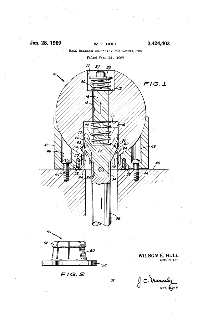
- The Ball-Shaped Mass (10)The deployable payload is a spherical mass with a hollow central bore (12), an upper recess (14), and a lower inverted bore (16).
- An internal annular groove (64) is machined into the lower interior cavity to serve as the locking catch for the spring fingers.
- The mass rides slidably on the internal actuating shaft rather than being rigidly bolted to the boom.
- The Resilient Spring Collar (54)Stationed inside the fixed mounting cup (43) on the satellite skin (48) is a dedicated collar equipped with flexible spring fingers (60).
- Each finger terminates in an outwardly bowed end portion (62).
- Crucially, the fingers are preformed with an inward natural bias—meaning when free of external pressure, they naturally spring radially inward and collapse away from the locking groove (64).
- The Actuating Shaft and Cam Land (18, 26, 30)The shaft connects directly to the tip of the extendible boom (38) via an attachment plug (34).
- The lower body of the shaft widens into an inverted frusto-conical portion (26) with an annular land (30) and a tapered sidewall (32).
- In the locked configuration, the land (30) wedges behind the spring fingers (60), wedging their bowed ends (62) outward into the groove (64) of the ball.
How the Mechanism Functions
The deployment sequence converts the linear extension of the satellite boom into a staged, shock-damped release:
| Step | Action | Operational Purpose |
| 1. Retracted Lock | The boom (38) sits fully retracted. The shaft’s land (30) forces spring fingers (60) outward into the mass’s annular groove (64). | Holds the ball-shaped mass rigidly seated in the cup-like support (43) during launch. |
| 2. Initial Boom Extension | The boom begins driving outward. The shaft (18) slides upward relative to the mass, sliding the land (30) away from fingers (60). | Disengages the wedging force holding the latches in place. |
| 3. Resilient Unlatching | The preformed spring fingers (60) snap radially inward toward each other under their own built-in spring tension. | Completely clears the bowed ends (62) from the groove (64), unlocking the mass from the cup. |
| 4. Free Deployment | The mass lifts away from the support cup (43) and rides outward into space on the extending boom. | Achieves separation with zero explosive shock or asymmetrical disturbance to satellite attitude. |
Key Mechanical Components
The mechanism balances positive seating against smooth kinetic separation using twin counter-acting springs:
- Cup-Like Support (43): Fixed rigidly to the satellite hull (48) by cap screws (44). It physically cradles the spherical mass while the craft is under high gravitational and launch loads.
- Upper Coil Spring (20): Located in the upper recess (14) between the bottom wall (15) and a retaining washer (22). It keeps the mass firmly preloaded against the support base while latched, and assists the initial forward slide of the shaft during separation.
- Lower Damping Spring (42): Positioned inside the lower bore (16) between the inner ceiling (17) and an annular recess (40) in the enlarged shaft portion (26).
- Dual-Spring Shock Mitigation: Working together, springs 20 and 42 prevent sudden snap-back forces when unlatching occurs and provide mechanical damping against vibrational oscillations as the payload moves into its final deployment position.
- Retraction Recapture: If the boom is pulled back in, the tapered sidewall (32) wedges back between the fingers (60), automatically camming them back out into the groove (64) to relatch the mass.
Technical and Aerospace Impact
Hull’s mechanism provided significant operational advantages for unmanned spacecraft:
- Shock-Free Attitude Preservation: In the zero-gravity environment of free space, explosive squibs or harsh spring releases induce torques that can tumble a spacecraft. Hull’s cam-and-finger unlatching is smooth and gradual, preserving satellite orientation.
- Reversibility: Unlike pyrotechnic separation nuts or cut-wire release devices that can only fire once, this mechanical geometry is fully resettable—extending unlocks the mass, while retracting the boom re-engages and locks it down.
- Integrated Oscillation Damping: By combining the lock-release cam with dual internal coil springs, the device solves both rigid retention and post-release vibrational damping within a single compact envelope.
About the Inventor: Wilson E. Hull
Wilson E. Hull was an aerospace engineer and inventor whose work contributed directly to mechanical and deployment systems developed during the 1960s space race. His mechanical latch designs focused on clean, repeatable kinematics under the extreme constraints of satellite operations, where thermal extremes, vacuum conditions, and attitude stability preclude complex electronic actuators or single-use destructive separation devices.
Summary of Claims
The patent explicitly claims:
- A mass release mechanism comprising a fixed support, a mass seated on the support, latching means on the support, and a sliding internal member cooperating to lock the mass.
- A resilient collar with fingers that are cammed radially outward to latch into the mass and preformed to snap radially inward when released.
- Resilient spring means (springs 20 and 42) operating to assist sliding unlatching, urge positive seating against the support, and damp mechanical oscillations of the payload mass at the end of an extendible boom.
