

Street Railway Switch (1890)
U.S. Patent No. 430,118, granted on June 17, 1890, to Philip B. Downing, introduced an ingenious mechanical system for operating track switches directly from a moving streetcar. Before this invention, switching a horse-drawn or electric streetcar often required the driver to stop, exit the vehicle, and manually throw a heavy iron switch with a crowbar or rod.
Downing’s design allowed for a “hands-free” transition from the main line to a siding, utilizing a combination of driver-controlled triggers and the natural weight of the car’s wheels to reset the tracks.
The Innovation: The “Vehicle-Actuated” Lever
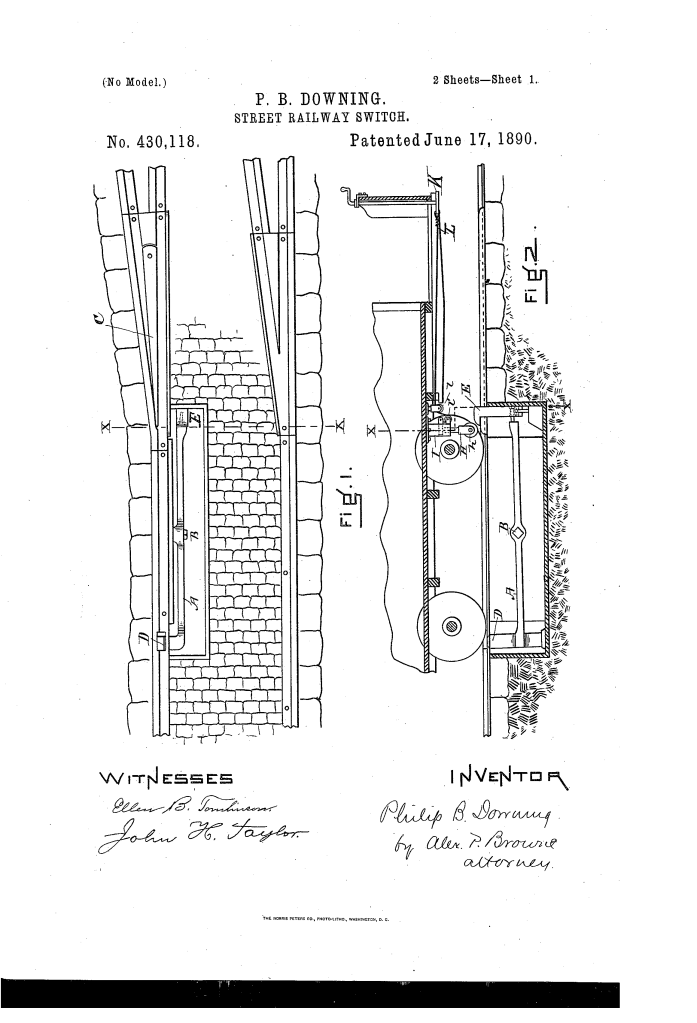
The heart of Downing’s invention is a long tilting switch-lever (A) buried in a vertical casing beneath the street level. This lever acts as a mechanical see-saw that controls the position of the switch-rail.
The system relies on two distinct vertical projections that interact with the car:
- The Forward Projection (E): A vertically sliding block located near the switch point. When depressed, it pulls the switch rail inward to open the path to the siding.
- The Rearward Projection (D): An extension located further down the track. This sits directly in the path of the car’s wheel tread.
How the Apparatus Functions
The process is designed to be cyclical, ensuring the switch is always reset for the next vehicle:
| Step | Action | Mechanical Result |
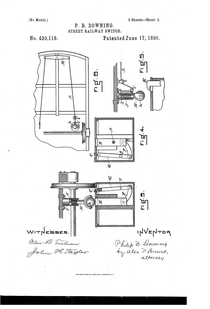
| 1. Activation | The driver depresses a foot pedal or handle to lower an arm (H) from the car’s underbody. | The arm strikes the Forward Projection (E), forcing it down. |
| 2. Shunting | A lever linked to the block oscillates, pulling the Switch-Rail (C) into the “open” position. | The car is diverted onto the side track. |
| 3. Automatic Reset | As the car passes, the rear wheel strikes the Rearward Projection (D). | This tilts the main lever back, raising the forward block and closing the switch for the next car. |
Key Technical Components
Downing’s patent focused on the precision of the mechanical linkages to ensure reliability under the heavy weight of streetcars:
- Switch-Operating Lever (A): Pivoted at point B, this long bar translates motion from the rear of the mechanism to the front.
- Operating Arm (H): A spring-loaded rod attached to the car, featuring an anti-friction roller (h) to prevent wear when it strikes the track components.
- The “Wheel-Base” Requirement: Downing specifically designed the distance between projections D and E to be longer than the car’s wheelbase. This prevents the back wheels from accidentally closing the switch while the front of the car is still passing through it.
Historical and Scientific Impact
Philip B. Downing’s street railway switch was a major step forward in urban transit efficiency:
- Operational Speed: By eliminating the need for drivers to dismount, transit systems could maintain tighter schedules and improve the flow of traffic in crowded cities like Boston and New York.
- Safety: It reduced the time drivers spent on the street between tracks—a dangerous location in busy intersections—and minimized the risk of manual switching errors.
- Evolution of the Industry: This patent was one of several contributions Downing made to the infrastructure of American life, showcasing a transition from simple manual labor to integrated mechanical automation.
About the Inventor: Philip B. Downing
Philip B. Downing was a prolific African American inventor based in Boston, Massachusetts.
- Legacy of Innovation: While best known for his 1891 patent for the street letter box (the precursor to the modern blue USPS mailbox), his work on railway switches demonstrated his deep understanding of complex mechanical systems and urban infrastructure.
- Family Heritage: Downing came from a prominent family of activists and entrepreneurs; his father, George T. Downing, was a well-known abolitionist and business leader.
- Versatility: His ability to solve problems in both the postal service and the transportation industry marked him as one of the most versatile inventors of the late 19th century.
Summary of Claims
The patent explicitly claims:
- A tilting switch-operating lever with vertical extensions at both ends to enable a see-saw mechanical action.
- A vertically movable block connected via a link and lever to the switch rail.
- The specific spatial arrangement of the extensions to ensure they are compatible with the vehicle’s wheelbase, preventing premature resetting of the switch.
