
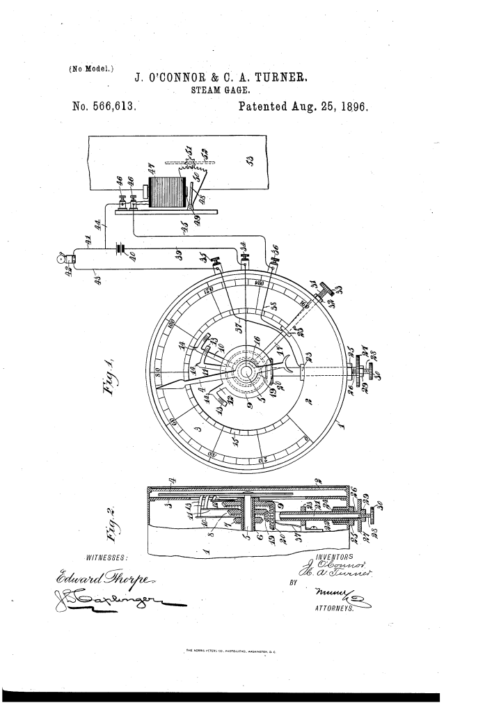
Steam-Gage with Automatic Alarm and Damper Control (1896)
U.S. Patent No. 566,613, granted on August 25, 1896, to John O’Connor and Collatinus A. Turner, describes an early automated safety system for steam boilers. John O’Connor and Collatinus A. Turner, inventors based in New York, N.Y., along with co-assignee David D. Turner of Jersey City, New Jersey, developed a way to integrate electrical contacts directly into a standard steam pressure gage.
This invention addressed a critical operational hazard of the industrial era: boiler explosions caused by undetected pressure surges or loss of pressure due to operator oversight. The apparatus not only triggers an audible alarm when steam pressure hits unsafe high or low limits, but it also automatically adjusts the boiler flue damper to regulate furnace draft and lower pressure without requiring human intervention.
The Innovation: Concentric Gear-Driven Adjustment Mechanism
Prior art steam gages with electrical contacts were difficult to adjust accurately or safely from the outside of the casing. O’Connor and Turner solved this by mounting multiple insulated, concentric bevel gear-wheels (7, 8, and 9) directly around the main pointer shaft (5).
These wheels carry movable contact arms that can be positioned at precise pressure readings on the dial. The true brilliance of the design lies in its external drive controls: nested shafts and sleeves extend through the side of the gage casing, allowing an operator to adjust and lock the contact triggers using thumb knobs and lock-nuts on the outside without opening the glass face or exposing the delicate internal mechanisms.
How the System Functions
The system acts as a dual-stage safety and regulation unit driven by the movement of the central pressure pointer:
- 1. Normal Pressure Tracking: As boiler pressure shifts, the central shaft (5) rotates, moving the main index or pointer (4) across the graduated annular scale (3).
- 2. Limit Alarms (High/Low): Adjustable fingers (11 and 12) are set to the upper and lower safe pressure thresholds. If steam pressure reaches either limit, pointer 4 contacts spring-arm 13 on finger 11 or 12. This completes an electric circuit powered by battery 40, sounding an alarm bell (42) to alert the engineer.
- 3. Automated Draft Control (Over-Pressure): A third finger (10) is set adjacent to or beyond the high-pressure limit. If pressure continues rising, pointer 4 makes contact with arm 13 of finger 10, completing a separate circuit through an electromagnet (47).
[Pointer (4) Touches Contact (10)] ➔ [Closes Electromagnet Circuit (47)] ➔ [Attracts Armature (48)] ➔ [Rotates Segment-Rack (50) & Pinion (51)] ➔ [Closes Flue Damper (52)]
When pressure subsequently drops back to safe operating levels, pointer 4 retreats, breaking the circuit. A counterweight on the external damper stem then automatically returns damper 52 to its open vertical position to restore normal draft.
Key Technical Components
The composition and layout of the mechanical and electrical assemblies include:
| Component | Function |
| Main Index / Pointer (4) | The primary pressure indicator; acts as the traveling positive contact for all internal electrical circuits. |
| Insulating Sleeve (6) | Electrically isolates the central rotating pointer shaft (5) from the surrounding contact wheels. |
| Bevel Gear-Wheels (7, 8, 9) | Concentric wheels of increasing diameter carrying radial fingers (10, 11, and 12) with rounded spring-arms (13) in the path of pointer 4. |
| Adjustment Shafts & Sleeves (17, 21, 22) | Transverse drive rods extending outside the casing, fitted with bevel pinions (16, 19, 20), external heads (27, 30), and lock-nuts (25, 29, 32) to set and secure contact points. |
| Binding-Posts (34, 35, 36) | External wiring terminals. Post 34 connects to the main casing and pointer; post 35 connects to alarm fingers 11/12; post 36 connects to damper finger 10. |
| Electromagnet & Armature Assembly (47–51) | Actuator mechanism consisting of magnet 47 and pivoted armature 48 with segment-rack 50 meshing with pinion 51 on damper stem 52. |
Performance and Operational Benefits
O’Connor and Turner’s patent provided clear practical advances for 19th-century steam plant operations:
- Low Resistance Contacts: Spring-arms 13 feature rounded ends, ensuring that when pointer 4 wipes across them to make electrical contact, minimum mechanical resistance is offered, maintaining accurate pressure readings.
- Dual-Scale Precision: Each adjustable finger features a pointed tip (14) that travels over a secondary inner scale (15), allowing precise visual alignment of trigger points against the main pressure scale (3).
- Fail-Safe Isolation: Internal wiring (37, 38) and insulated bearings (23, 23a, 24) prevent short circuits to the metal casing 1, ensuring reliability in high-humidity boiler room environments.
Historical and Industrial Context
During the late 19th century, steam power drove manufacturing, transportation, and building heating, but catastrophic boiler explosions were a frequent occurrence due to over-pressurization and human error.
- Early Automation: This patent represents an important step in the evolution from manual boiler monitoring to automated closed-loop control systems.
- Electromechanical Integration: By combining a traditional Bourdon-style mechanical pressure gage with an electromechanical relay system, the inventors created a early hybrid device that could both display status and actively remediate dangerous conditions.
About the Inventors
- John O’Connor and Collatinus A. Turner: Innovators based in New York City during the peak of American industrial expansion.
- Collaborative Development: Working alongside co-assignee David D. Turner of Jersey City, their work focused on practical safety enhancements for steam infrastructure that could be manufactured cheaply and retrofitted into existing steam plant designs.
Summary of Claims
The patent explicitly claims:
- The combination of a steam gage casing, scale, central rotating shaft, and pointer with an insulated sleeve carrying a gear-driven contact arm positioned in the pointer’s path to close an electrical circuit.
- The use of nested, insulated external shafts, sleeves, and bevel gear sets to adjust multiple independent contact arms from outside the gage casing.
- The integration of the gage contact mechanism with an electromagnet circuit that mechanically drives a segment-rack and pinion assembly to operate a boiler flue damper.
