
Steam-Trap (Henry Creamer, No. 376,586)
The patent by Henry Creamer of New York, N. Y., describes an improved Steam-Trap (Patent No. 376,586, 1888). This invention is a mechanical device used in steam heating and power systems to automatically collect water of condensation and force it back into a boiler. Creamer’s primary objective was to provide an automatic regulator that is simple and effective, governed entirely by the volume of water collected within the trap itself.
Inventor Background: Henry Creamer
Henry Creamer was an African American inventor and engineer based in New York City during the late 19th century. His work focused on the efficiency of steam-power systems, which were the backbone of industrial and domestic heating at the time. This 1888 patent is an evolution of his earlier work on feed-water traps. Creamer was known for his mastery of piston-driven mechanics and automated valve regulation, creating systems that reduced the need for manual monitoring of boilers and increased the overall safety of steam-operated machinery.
Key Mechanical Components & Functions
The trap is built around a combined steam and water cylinder, utilizing a unique floating cup to trigger the return stroke.
1. The Steam and Water Cylinders (A, B)
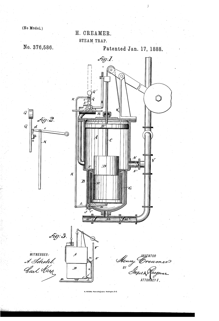
- United Housing: The steam-cylinder (A) and water-cylinder (B) are typically joined as a single unit.
- The Neck (E): A neck or sleeve (E) projects from the bottom of the steam-cylinder down into the water-cylinder.
- The Pistons (B, D): A steam-piston (B) in the upper cylinder is connected via a rod (C) to a water-forcing piston (D) that works inside the neck (E).
2. The Open-Top Float (G) (Key Innovation)
- Cup-Shaped Design: Between the central neck and the outer wall of the water-cylinder sits an open-top or cup-shaped float (G).
- Vertical Movement: This float is capable of moving up and down a short distance based on the water level.
- Lever Connection: The bottom of the float is pivoted to a lever (H) connected to a shaft (J) and a vertical rod (K).
3. The Automatic Valve Regulator (Q, c, d)
The movement of the float controls the steam that drives the pistons.
- Weighted Rocking Lever (Q): This lever shifts the valve rod (R) to control steam admission. It features a wing with a laterally-projecting lug (b).
- Latch Lever (c): A separate lever (c) at the top of the cylinder carries a latch (d).
- Function: This latch acts as a “trigger.” When the float is raised, the rod (K) moves the latch to lock or release the weighted lever (Q).
Operation: The Forcing Cycle
The trap operates in a continuous cycle driven by the accumulation of condensation.
- Filling: Water of condensation enters the bottom of the water-cylinder via pipe (M). As the water level rises, it overflows into the open-top float (G).
- Tripping: The weight of the water in the float causes it to sink. This pulls the rod (K) upward, which disengages the latch (d) from the lug (b).
- The Downward Stroke: The weighted lever (Q) swings, shifting the valve to admit steam to the top of the steam-cylinder. The piston (D) is forced down into the neck and the float.
- Action: This forces the water out of the float and through the pipes back into the boiler. The float is supported and “cushioned” by the water below it during this high-pressure event.
- Reset: Once the stroke is complete, the valve is reversed. Steam enters the bottom of the cylinder to raise the pistons. The upward pressure of the incoming water lifts the float, re-engaging the latch and stopping the mechanism until the float fills again.
Improvements Over Previous Steam Traps
| Feature | Standard 1880s Traps | Creamer’s Steam-Trap |
| Regulation | Required external manual or complex spring regulators. | Governed entirely by the volume of water in the internal float. |
| Durability | Floats often collapsed under steam pressure. | Open-top float is “cushioned” by water on both sides to prevent crushing. |
| Efficiency | Prone to “stalling” or irregular cycling. | Precise latch mechanism (d) ensures a full, powerful forcing stroke. |
| Maintenance | Complex multi-piece housings. | Simplified design with a united cylinder and integrated neck (E). |
Significance to Mechanical Engineering
Henry Creamer’s steam-trap influenced the development of automated boiler feed systems and fluid-level logic.
- Hydrostatic Balancing: Creamer’s method of using the water inside the cylinder to “support” the float against high-pressure steam is an early application of hydrostatic balancing, essential for modern deep-sea and high-pressure valves.
- Mechanical Logic Gates: The latch-and-lug system acts as a mechanical “if-then” statement (if float is heavy, then fire piston), a foundational concept in automatic control theory.
- Condensate Management: His trap helped standardize the practice of returning high-temperature water of condensation directly to the boiler, significantly increasing the thermal efficiency of industrial steam plants.
- Space-Saving Design: By nesting the water-forcing piston inside a neck that fits inside the float, Creamer pioneered the concentric assembly techniques used in modern hydraulic struts and shocks.
Would you like to explore other patents by Henry Creamer, such as his work on steam-pumps or his water-level indicators?
