
Steam-Boiler (Benjamin F. Jackson, No. 690,730)
The patent by Benjamin F. Jackson of North Cambridge, Massachusetts, describes new and useful Improvements in Steam-Boilers (Patent No. 690,730, 1902). The invention aims to combine the strength of a cylindrical shell with the advantages of the water-tube system, providing a boiler suitable for motor-vehicles that is less prone to injury and more efficient at superheating steam.
Inventor Background: Benjamin F. Jackson
Benjamin F. Jackson was an inventor specializing in thermal and combustion engineering, known for his work on high-efficiency gas burners.1 This patent is part of his sustained effort to improve motive power and heating technology, focusing here on optimizing the water-tube boiler for the constraints of early motor vehicles.
Invention and Mechanism
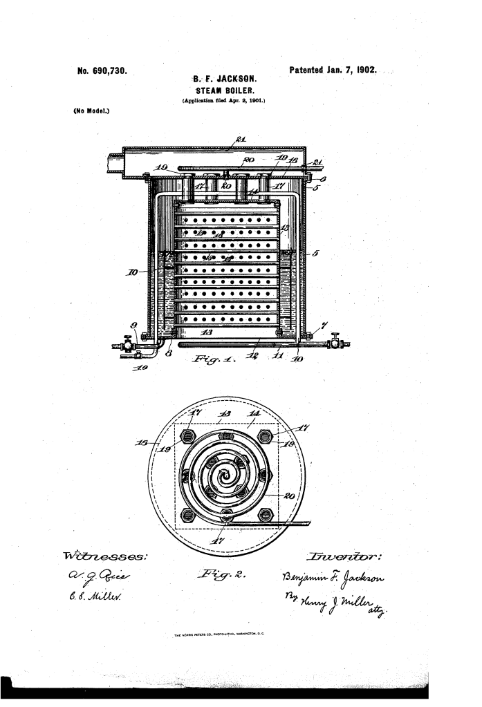
The boiler uses an inner, rectangular water-tube chamber secured within a strong, cylindrical outer shell to maximize heat transfer and superheating capacity.
1. Hybrid Boiler Structure (Key Innovation)
- Cylindrical Shell (5): The strong outer casing, which serves as the water reservoir (lower portion) and steam-dome (upper portion). This shape maximizes strength.
- Rectangular Tube-Chamber (12): A chamber with cross layers of water-tubes (15, 16) secured inside the shell’s central opening.
- Function: This rectangular shape, combined with the cylindrical shell, creates a large volume of water located at the open ends of the tubes, which improves the circulation of water through the tubes and diminishes foaming.
- Bracing: The rectangular chamber’s top (14) is secured to a crown-sheet (18) by nuts (19) that screw onto flues (17) passing through the sheet, creating a strong brace.
2. Superheating Mechanism
- Flues (17): A series of flues extend from the tube-chamber (12) up through the crown-sheet (18). Hot combustion gases pass through these flues.
- Steam-Supply Pipe (20) Coiled: The steam-supply pipe has its open end near the flues and is coiled above the open ends of the flues (17).
- Function: As steam rises, it passes between the heated flues (17), superheating the steam. The pipe’s coil (20) receives the hottest gases passing through the flues, causing further superheating and delivering highly expansive steam.
3. Fluid Fuel Safety (Vaporization)
- Fuel-Supply Pipe (10): The fluid fuel pipe passes through the water-shell of the boiler and over the tube-chamber.
- Function: The pipe is subjected to sufficient heat to thoroughly vaporize the fuel (pre-heating). Crucially, if there is an accidental leakage of fuel, it will be received into the boiler-shell and cannot pass to the furnace, addressing a major safety concern with early motor-vehicle fluid-fuel systems.
Concepts Influenced by This Invention
Jackson’s boiler influenced subsequent designs in high-pressure and mobile power systems by establishing principles for integrated superheating and internal fluid safety.
- Integrated Superheating Coil: The concept of using flues (17) that pass hot gases through the steam dome and a coiled steam-supply pipe (20) located directly in the exhaust path to achieve advanced superheating influenced the design of high-efficiency industrial and marine boilers.
- Internal Leak Containment (Vaporization Safety): The strategy of running the fluid fuel line (10) through the non-combustion space (the water-shell) influenced safety engineering in power systems. This design ensures that any leak of volatile fuel is immediately contained and neutralized by the surrounding fluid (water), preventing hazardous leakage into the furnace.
- Hybrid Structural Design: The combination of a strong cylindrical pressure vessel (shell 5) with an internal, efficiency-maximizing rectangular heat-exchange unit (chamber 12) influenced the design of specialized industrial heat exchangers and pressure vessels where different internal geometries are required for optimal function within a strong external housing.
- Easy Access for Repair: The use of nuts (19) to secure the crown-sheet (18) facilitates the removal of the crown-sheet for easy access to the interior for examination and repair of the tubes.
