
Stairclimbing Wheelchair (1968)
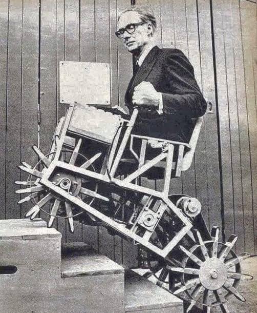
U.S. Patent No. 3,411,598, granted on November 19, 1968, to Rufus J. Weaver, describes a self-propelled stair-climbing mechanism integrated with an ambulatory wheelchair. Rufus J. Weaver, an inventor residing at 14 East Street in New London, Connecticut, developed a mechanical system that could negotiate flights of stairs step-by-step while maintaining occupant stability, transforming smoothly back into a standard rolling wheelchair on level floors.
This invention solved a critical mobility challenge: how to empower individuals using wheelchairs to safely ascend and descend multi-step staircases without structural building ramps or external physical assistance, all while preventing accidental falls or tip-overs.
The Innovation: The Alternating Step-Contoured Carriage
Traditional attempts at stair-climbing wheelchairs relied on continuous rubber tank tracks, multi-wheel star clusters, or manual attendant winches. These mechanisms were often prone to slippage on stair edges, lacked positive mechanical locking, and handled transitions at the top and bottom landings poorly.
Weaver took a fundamentally different approach. Instead of rolling over the steps, his mechanism walks up or down them by using two nested, complementary structures that physically replicate the negative profile of standard stair treads and risers.
How Alternating Eccentric Drive Works
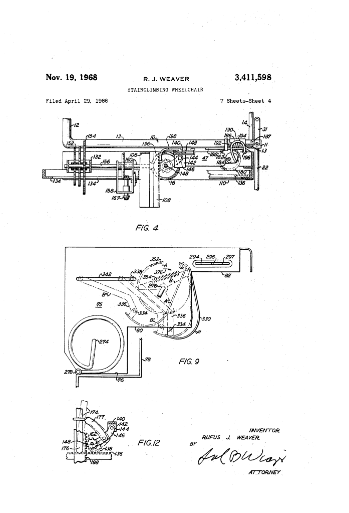
- Step-Contoured Housing (75): A central drive housing, called the “box,” features a underside molded into stepped tiers (76, 80, 82) and riser stops (77, 81) that seat flush onto two, three, or more stairs simultaneously.
- Matched Side Rails (78): Positioned on either lateral side of the central box are parallel tracking rails contoured to match the exact same stair profile.
- Synchronous Eccentric Rotation: Output drive shafts (274, 276) drive crank pins (278, 280) through resilient arcuate crank arms (282, 284). As the shafts turn:
- First Phase: With the side rails resting firmly on the steps to act as a stationary foundation, the rotating crank pins lift the central housing vertically and rearward, depositing it onto the next step up.
- Second Phase: With the central housing now firmly seated and bearing the vehicle’s weight, continued rotation causes the crank pins to lift the lateral rails off the steps, swinging them up and rearward to seat alongside the housing on the new step.
Key Mechanical Components
Weaver’s design integrates three distinct mechanical subsystems into a unified platform:
| Component | Identifier | Mechanical Function |
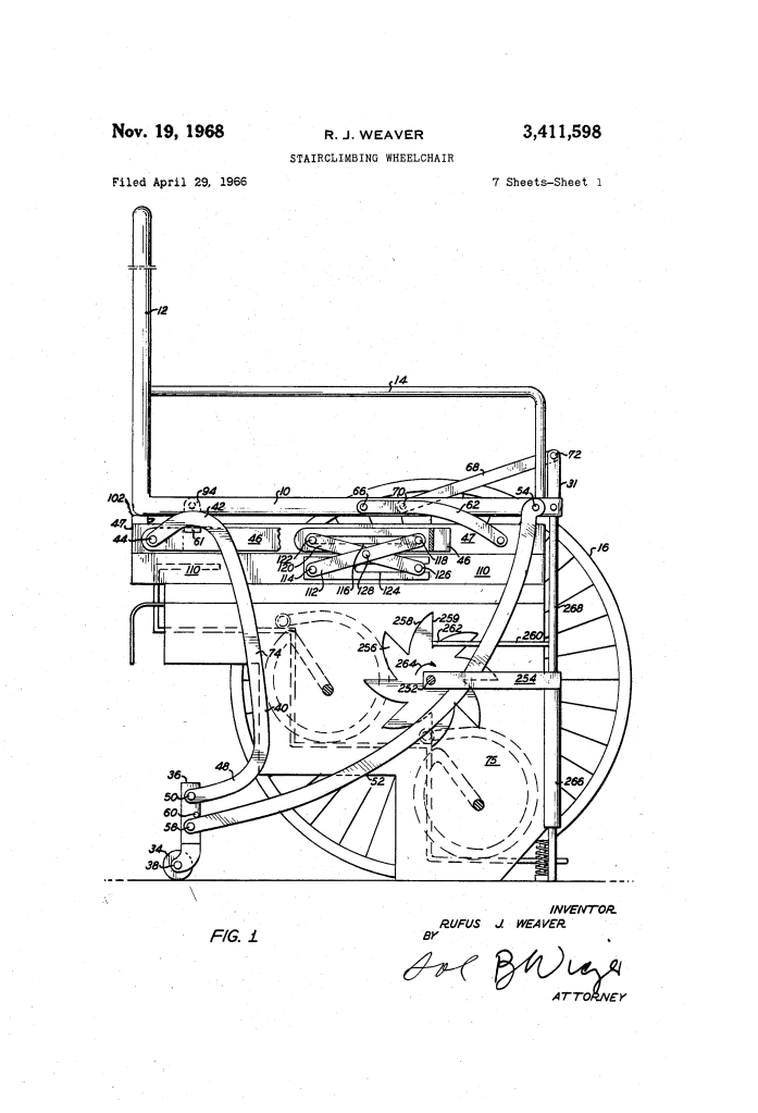
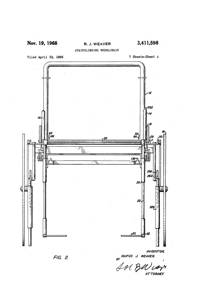
| Step-Contoured Housing | 75 | Central chassis shaped to match three consecutive stair steps (76, 80, 82); houses climbing motor 300 and gear train 308. |
| Lateral Stepped Rails | 78 | Paired tracking rails matching stair riser/tread profiles; alternate with housing 75 as load-bearing ground supports during climbing. |
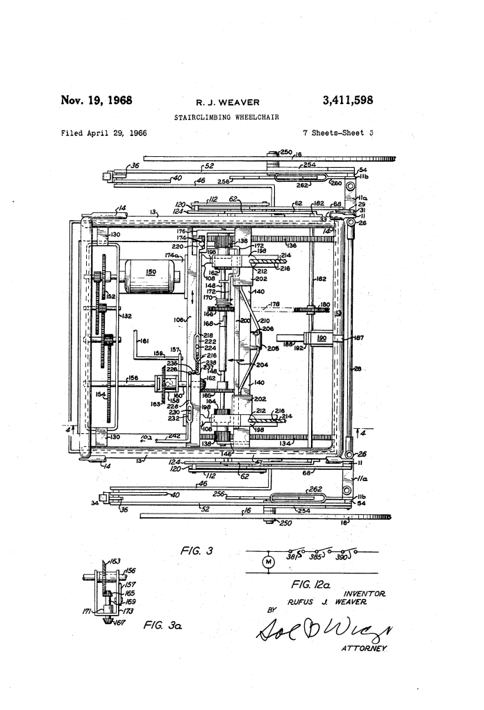
| Lazy-Tong Lift Assembly | 112, 120 | Scissor-action linkage that raises and lowers lower frame 110 and climbing box 75 relative to the upper wheelchair frame 47. |
| Horizontal Rack and Pinion | 136, 138 | Sliding rack mechanism that shifts climbing box 75 rearward to clear the main wheels and seat onto the stairs. |
| Chair Tilting Linkage | 62, 68, 182 | Power-driven pivot arm network that tilts the seat back to balance the passenger’s center of gravity and elevate the wheels. |
| Folding Rear Wheel Braces | 36, 40, 52 | Retractable support arms that swing rear casters 34 up into a horizontal clearance position when the chair tilts. |
| Auto-Deploying Backdrop | 362, 364 | Foldout stabilizer prop that lowers automatically at the top landing to support the upper end of the box over open floor space. |
| Floor-Sensing Wheel Brake | 256, 260, 268 | Drop-rod gravity sensor (268) that instantly engages locking sprocket teeth (256) if floor support terminates (e.g., at the edge of a step). |
Operational Transition: From Wheelchair to Stair Climber
Preparing the apparatus for climbing requires a sequenced conversion managed by control lever 174 and motor 150:
[Level Ambulatory Mode] │ ▼1. Position at Bottom Riser: Back chair until rear wheels 34 touch the first step riser 77. │ ▼2. Extend Climbing Box: Engage horizontal rack gears 136 to slide box 75 rearward over the steps. │ ▼3. Lower Box to Stairs: Shift lever 174 to lower box 75 via lazy-tong linkages (112, 120) until it rests on the lower three steps. │ ▼4. Tilt and Balance Seat: Engage clutch 168 to rotate tilt shaft 182. Chair tilts backward on pivot arms 62; side wheels 16 and rear casters 34 swing up clear of the staircase; lock pin 242 drops behind rear corner 102 to lock tilt angle. │ ▼5. Re-Center and Lock: Shift tilted chair back along sliding frame 110 directly over the center of gravity of box 75, then lower upper frame 47 flush onto box 75. │ ▼[Stair Climbing Mode: Motor 300 drives alternating steps via crank arms 282, 284]
Safety and Landing Systems
Climbing steep staircases introduces unique balance and tipping hazards. Weaver incorporated several automatic mechanical and electrical interlocks:
- Automatic Top Landing Backdrop (362): During the climb, a spring-loaded trigger arm (330) rides along the stair tread surfaces, holding sliding shaft 338 disengaged. When the top of the stairs is cleared, trigger arm 330 drops off the step edge. This allows spur gear 350 to mesh with sectional gear 352, swinging prop arm 364 downward into firm contact with the floor to prevent backward tipping.
- Automatic Electrical Cutout: Lowering the backdrop swings switch arm 294 out through slot 296 into the travel path of track 78. When track 78 finishes its final climbing rotation, it strikes arm 294, bending hinge 299 to break electrical contact 295 and shut down climbing motor 300 immediately.
- Floor-Sensing Fall Arrest: At the edge of a landing, gravity drop-rod 268 senses the presence of the floor. If the floor surface drops away, rod 268 falls, forcing locking bar 260 and frame 262 down against vertical locking teeth 259 on wheel hub sprocket 256, mechanically locking the wheels against forward rotation toward the staircase.
About the Inventor: Rufus J. Weaver
Rufus J. Weaver was an independent inventor based in New London, Connecticut. During the post-World War II period and the early stages of the modern disability rights and assistive technology movements, independent mechanical inventors like Weaver led the way in developing complex ambulatory mechanisms.
- Kinematic Design: Weaver’s patent demonstrates advanced mechanical engineering, seamlessly combining four-bar links, lazy-tong scissor elevators, swinging countershaft gear couplings, and dual-output eccentric crank drives into a single unified chassis.
- Legacy: Weaver’s alternating-frame concept laid key foundational groundwork for later stair-climbing mobile robotics and modern powered mobility devices (such as Dean Kamen’s later iBOT system), proving that stepped geometry could provide positive, non-slip stability on varied stair profiles.
Summary of Claims
The patent explicitly claims:
- A stair climbing and descending mechanism comprising a housing and complementary side tracks, each shaped to conform to multiple steps and risers of a staircase, driven eccentrically and synchronously to lift the housing and tracks in alternating cycles.
- The combination of the stair-traversing unit with an ambulatory wheelchair, including mechanisms for raising, lowering, and sliding the climbing box relative to the chair frame.
- A chair-tilting linkage that shifts the occupant’s weight backward into a stable center of balance while simultaneously retracting the wheels out of ground-engaging position.
- An automatic rear-prop backdrop actuated by a step-sensing trigger arm to level and support the chassis upon reaching the top landing of a staircase.
- A floor-level sensing brake assembly configured to lock the ambulatory wheels against forward rotation whenever floor support beneath the chair terminates.
