
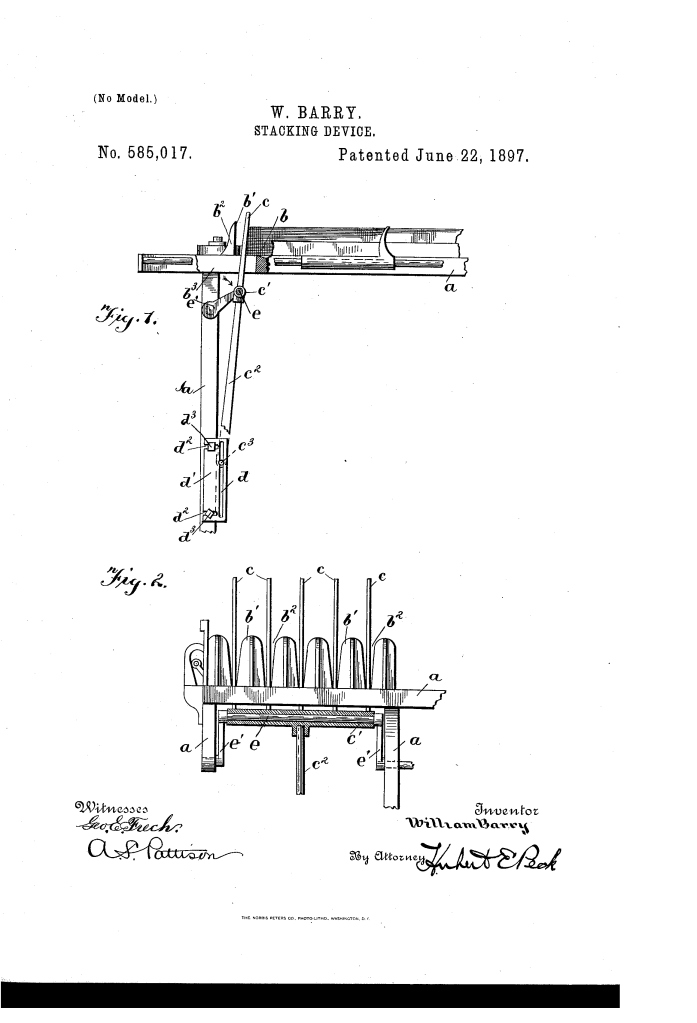
Stacking Device (1897)
U.S. Patent No. 585,017, granted on June 22, 1897, to William Barry, describes a specialized mechanical pusher and stacking mechanism designed for high-speed mail-marking machines. Operating out of Syracuse, New York, Barry developed this apparatus to solve a common bottleneck in early automated mail processing: how to rapidly, reliably, and continuously stack vertically discharged letters without jamming or interrupting the flow of oncoming mail.
This invention addressed the physical challenge of moving flexible, varied pieces of mail out of the entry path immediately after cancellation or postmarking, neatly consolidating them against a growing stack in an orderly receiving-way.
The Innovation: The “Elliptical Stroke” Stacker
Automated postmarking machines discharged letters in an upright position at rapid intervals. If a letter lingered in the entry slot, the subsequent letter would collide with it, causing paper jams and damaging the mail. Earlier pushers often used rigid reciprocating plungers that risked catching incoming mail on the return stroke.
Barry’s breakthrough was a swinging, crank-driven stacking finger assembly that travels along an elliptical or encircling path. Instead of retreating back along the same track, the fingers rise up through the slotted floor, press the letter flat against the mail stack, retreat downward below the floor line, and circle back underneath the receiving-way to reset behind the next incoming piece.
Why the Elliptical Path?
- Clear Intake: The fingers drop beneath the floor of the way during the return stroke, preventing any interference with the next discharged letter.
- Continuous Flow: The cyclic crank action transforms constant rotational drive into a smooth, rhythmic pushing movement.
- Adjustable Throw: By shifting the mounting plate of the lower sliding pivot, an operator can adjust the horizontal stroke length to suit different operational requirements.
Technical Components
The stacking mechanism relies on an integrated arrangement of guiding slots, a pivoting framework, and a direct crank-drive:
| Component | Function |
| Receiving-Way (b) | The collection trough where letters arrive upright; features vertical slots in the front wall (b2) and elongated floor slots (b3). |
| Pusher Fingers (c) | A series of rigid vertical slats that sweep through the slots to press against the flat face of each letter. |
| Tubular Cross-Head (c’) | A horizontal sleeve positioned beneath the floor that rigidly holds the pusher fingers and houses the drive shaft. |
| Shank and Pivot (c2, c3) | A downward-extending body ending in a lateral pintle that serves as the traveling fulcrum for the swinging stacker. |
| Guide Plate (d’) | A frame-mounted plate with a vertical guide slot (d) that confines the sliding pivot, adjustable via horizontal slots (d2) and bolts (d3). |
| Crank-Shaft (e, e’) | A revolving drive shaft passing through the cross-head with offset cranks that power the pusher’s elliptical arc. |
How the Stacking Cycle Operates
The mechanism executes a four-phase movement cycle timed to the arrival of each postmarked letter:
- Emergence: Driven by the revolving crank-shaft (e), the upright fingers (c) rise up through the elongated floor slots (b3) directly behind a newly arrived letter.
- Forward Drive: The fingers advance through the front wall slots (b2), engaging the flat face of the mailpiece and pushing it firmly against the accumulated stack.
- Submersion: As the crank completes its forward throw, the pusher assembly tilts downward on its traveling fulcrum (c3), lowering the fingers beneath the floor surface.
- Reset: Traveling below the plane of the receiving-way, the fingers sweep back to their starting position, ready to rise behind the next piece of mail entering the queue.
Industrial and Practical Impact
William Barry’s stacking mechanism provided a reliable mechanical solution for the expanding postal demands of the late 19th century.
- Anti-Jam Operation: By clearing the intake zone and descending below the path of travel before retreating, the design eliminated collisions between processed and incoming mail.
- Mechanical Simplicity: The device combined propulsion and motion-guiding into a single crank-and-slotted-fulcrum linkage, minimizing the number of wearing parts.
- Adaptability: The laterally adjustable guide plate (d’) allowed maintenance mechanics to calibrate the lateral reach and stroke depth without re-machining the frame.
About the Inventor: William Barry
William Barry was an inventor based in Syracuse, New York, active during the late 19th-century boom in postal automation and light machinery. His contributions to mail-marking equipment focused on the mechanical interface between high-speed automated feeds and physical sorting trays, helping postal departments and private handling services manage the surging volumes of domestic and commercial correspondence.
Summary of Claims
The patent explicitly claims:
- The combination of a frame, a receiving-way with a slotted floor and front wall, and a swinging pusher movable through the slots via a rotary actuator.
- A stacker comprising a tubular cross-head with rigid vertical fingers and a downward shank confined to an elongated vertical guide.
- The movement of letter-engaging fingers along an encircling or elliptical path into, through, and beneath the receiving plane.
- An adjustable guide member beneath the frame that alters the position of the fulcrum to calibrate the throw of the pusher.
