
Balanced Slide-Valve (1897)
U.S. Patent No. 585,798, granted on July 6, 1897, to Benjamin H. Taylor, addresses a fundamental inefficiency in steam engine mechanics: the excess bulk, friction, and pressure management issues inherent in conventional steam-chest assemblies.
In standard steam engines of the late 19th century, large external steam chests enclosed the valve mechanism, creating heavy, unbalanced downward pressures that caused excessive wear and required substantial energy to operate. Taylor, an inventor based in Rosedale, Mississippi, designed an integrated system that eliminated the traditional steam chest entirely, routing live steam directly into the interior of a hollow valve body while providing precise mechanical regulation over valve seating and balance.
The Innovation: The Combined Valve and Steam-Chest
Taylor’s breakthrough was the elimination of the separate steam-chest housing by engineering the slide valve to function as its own internal steam reservoir.
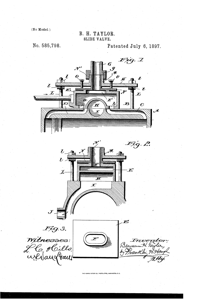
Direct Steam Ingress: Live steam enters directly into the hollow interior of the valve through an elongated top opening (F) that remains aligned with the inlet pipe (G) throughout the entire stroke of the valve.
Dual-Action Porting: As the valve moves back and forth, its internal supply ports (a, b) align alternately with the engine cylinder ports (C, D) to drive the piston, while a central semicircular exhaust chamber (H) directs spent steam out through the exhaust port (I) and side outlet (J).
Integrated Pressure Regulation: Instead of letting unmanaged boiler pressure force the valve down against its seat, Taylor introduced an adjustable dual-plate suspension system to balance operational loads.
The Dual-Adjustment Pressure System
To prevent steam leaks without causing binding or friction wear on the ground seat, Taylor implemented a two-tier mechanical adjustment system:
- Fixed Adjustable Plate (K)Mounted directly to the cylinder on threaded vertical posts (L) and secured above and below by jam-nuts (Z). This plate forms the rigid structural bridge for the steam line and provides coarse height positioning.
- Floating Pressure Plate (N)Positioned directly beneath Plate K, this plate rests against the upper face of the slide valve. It features an upward-projecting tubular collar (N’) that slides telescopically inside the collar (M) of Plate K.
- Regulating Set-Screws (O)Threaded through Plate K to exert direct, finely calibrated downward force against Plate N. This allows engineers to tune the exact seating pressure of the valve without requiring long, unwieldy adjustment screws.
How the Mechanism Operates
| Step | Action | Mechanical Purpose |
| 1. Steam Supply | Live steam enters through vertical pipe (G) into elongated slot (F). | Delivers continuous steam volume into the moving valve without an external chest. |
| 2. Intake Cycle | Valve slides until lower port (a or b) aligns with cylinder port (C or D). | Injects steam directly into the active end of the cylinder to drive the piston stroke. |
| 3. Exhaust Cycle | Semicircular chamber (H) bridges the inactive cylinder port with exhaust port (I). | Expels spent steam cleanly out the lateral outlet (J). |
| 4. Wear Adjustment | Operator tightens jam-nuts (Z) or turns set-screws (O). | Closes gaps from wear and stops steam leakage without binding the valve mechanism. |
Key Technical Components
- Engine Cylinder (A): Standard steam cylinder with ground level valve seat (B) on its upper surface.
- Combined Slide-Valve (E): Hollow box chamber housing the live steam supply and central exhaust arch (H).
- Telescoping Steam Collars (M, N’): Overlapping tubular sleeves that maintain a steam-tight path between the stationary supply line and the moving valve body.
- Threaded Support Posts (L): Anchor studs rising from the cylinder body to hold the adjustable mounting bridge.
Engineering Significance
Benjamin H. Taylor’s balanced slide-valve represented an important mechanical optimization for industrial and locomotive steam plants during the height of the American industrial era.
Friction Reduction: By balancing the internal steam pressure against an adjustable overhead plate rather than leaving the valve exposed to an open steam chest, the design substantially reduced parasitic frictional drag on the engine.
Maintenance Efficiency: The double-adjustment assembly enabled mechanics to quickly tighten slack components using compact set-screws and jam-nuts rather than dismantling large boiler-grade housings.
Compact Footprint: Eliminating the bulky steam chest reduced raw material costs and reduced the overall profile and weight of the cylinder head assembly.
About the Inventor: Benjamin H. Taylor
Benjamin Henderson Taylor was an inventor residing in Bolivar County, Mississippi, during the post-Reconstruction era. His work on fluid dynamics and steam-engine efficiency reflects the vital contributions of Southern inventors aiming to optimize heavy machinery, agricultural processing mills, and river transport networks through practical mechanical innovations.
Summary of Claims
The patent explicitly claims:
- A steam engine cylinder featuring a top-mounted valve seat paired with a hollow valve serving simultaneously as a slide-valve and steam-chest.
- The vertically adjustable lower plate (N) equipped with a tubular collar (N’) acting as a steam-pipe conduit.
- The upper adjustable plate (K) with an integral collar (M) aligned with the primary steam inlet.
- The combination of threaded cylinder posts (L), jam-nuts (Z), and regulating set-screws (O) providing dual-stage pressure control over the valve.
