
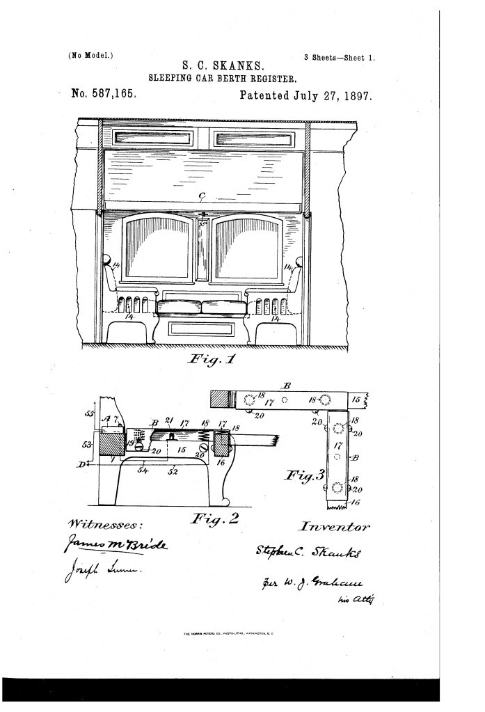
Electric Sleeping-Car-Berth Register (1897)
U.S. Patent No. 587,165, granted on July 27, 1897, to Stephen Chambers Skanks, describes an automated electrical recording system designed to register the occupancy of sleeping-car berths on passenger trains. Skanks, an inventor based in Toronto, Ontario, Canada, developed the mechanism to ensure accurate, tamper-proof accounting of berth usage on overnight railway journeys.
The invention addressed a persistent logistical and revenue-tracking challenge for railway operations: verifying whether upper and lower berths were actually occupied by paying passengers each night, preventing unrecorded cash transactions by conductors or porters, and automatically distinguishing between nighttime occupancy and routine daytime maintenance.
The Core Innovation: Automated Nighttime Verification
Sleeping-car sections convert between daytime seating benches and stacked nighttime berths. Skanks devised an integrated system of electromechanical contacts, magnetic circuit-breakers, and central indicator dials that recorded usage automatically without requiring human reporting.
Key Mechanical Subsystems:
- Lower Berth Automatic Seat Contact and Circuit Breaker (A, B)
- Seat-Frame Contact (B): A slotted channel-plate (17) supported by springs (18) is set into the seat rail. When a passenger’s weight settles onto the cushions, the plate is pushed down against a stationary metallic contact stud (21), closing the initial electrical circuit.
- Magnetic Cut-Off Box (A): Mounted on the rear rail (1), this casing contains a pair of electromagnets (3), an L-shaped armature (5), a pivoting lever (6), and contact springs (8, 9). The very first compression triggers the indicator dial while instantly energizing the electromagnets (3). This pulls the armature (5) and breaks the circuit, ensuring that subsequent movements or shifts in the night do not register multiple times.
- Daytime Lockout: A spring-loaded compression bolt (7) extends from casing (2). During daytime operation, the upright back-cushion (14) rests directly against the bolt, mechanically holding the contact springs (8, 9) apart to prevent accidental registration while seats are in normal daytime use.
- Upper Berth Spring Plunger Contact (C)
- Plunger Assembly: Concealed inside one of the primary mattress-support spiral springs (22), a central chamber (25) houses an internal vertical shank (27) held under tension by spring (28) beneath a movable cap (26).
- Single-Action Catch: When the passenger first lies on the mattress, cap (26) depresses, forcing a projection (36) on the shank to deflect contact spring (37) into spring (38) to close the circuit to dial (50).
- Locking Bolt (30): As the shank hits the bottom of its stroke, a spring-actuated bolt (30) snaps into a catch recess (32). This keeps the plunger locked in the down position until the upper berth is fully latched closed again via the main berth handle (35a), preventing repetitive false triggers if the passenger enters and exits during the night.
- Upper Berth Anti-Fraud Counterweight SystemTo prevent fraud where an upper berth was closed up during the night to give a lower berth occupant extra head space without officially recording the car layout change:
- A chain (42) secured to the upper berth hinge-rail (41) suspends a sliding weight (43) that travels along a fixed vertical guide rod (45) inside the car wall.
- The weight features a spring-actuated arm (46) with a directional stop-joint (46a). When the berth is closed during the night (with the lower seat cushion removed), the descending weight engages contact springs (48, 49), registering a closure on the central dial (50).
Technical Components and Circuit Connections
| Component | Patent Callout | Functional Role |
| Lower Circuit Breaker | Device A (casing 2, magnets 3, armature 5, lever 6) | Senses cushion depression and breaks the circuit after one pulse to prevent redundant counts. |
| Daytime Cutout Bolt | Compression Bolt 7 | Held down by back cushion 14 during the day to keep circuits open and inert. |
| Lower Rail Contact | Device B (plate 17, springs 18, stud 21) | Direct weight-sensing switch installed on seat frame rail 15/16. |
| Upper Berth Plunger | Assembly C (chamber 25, cap 26, shank 27, bolt 30) | Spring-caged switch that triggers once upon initial weight and latches closed. |
| Berth Closure Sensor | Weight 43, Arm 46, Springs 48 & 49 | Mechanically records upper-berth stowage when lower berth is prepared for sleep. |
| Central Indicator Dials | Dials 50 & 51 | Remote counters located in a secure locker accessible only to authorized rail inspectors. |
| Power Source | Battery D | Operates on the closed metallic loop system already wired for train car call-bells. |
Operational Flow
The system routes electric currents through distinct closed pathways depending on passenger behavior:
- Lower Berth Occupancy: When the passenger reclines, plate (17) contacts stud (21). Current flows from Battery D along wire 52, through the contact, via wire 54 into magnets (3), through wire 58, armature (5), lever (6), wire 57, into lower berth register (51), and returns through battery wire E. The magnets pull armature (5), immediately breaking circuit continuity to lock the count at one.
- Upper Berth Occupancy: Weight on mattress (23) pushes cap (26) down. Projection (36) brings spring (37) into spring (38). Current flows through main wire F, branch wire 39, through closed springs (38, 37), wire 40, to upper berth register (50), and returns via wire E. Bolt (30) catches shank (27) to silence further contact pulses.
- Unoccupied Upper Berth Stowage: If the upper berth is closed during the night without an occupant, the descending weight (43) forces arm (46) against springs (48, 49). Current flows through wire F, branch 53, lower switch springs (9, 8), wire 55, springs (48, 49), wire 56, and to register (50), accounting for the berth state on the dial.
- Daytime Reset: In the morning, re-inserting seat back-cushion (14) depresses bolt (7), disconnecting springs (9, 8). This isolates the circuit so maintenance crews can open and close the upper berths repeatedly to stow bedding without advancing the registers.
Historical and Industrial Significance
Stephen Chambers Skanks’s patent represents a sophisticated late 19th-century application of automated electromechanical auditing in railway transit:
- Fraud Prevention: Sleeping-car operations like the Pullman Company operated on complex fare structures where conductors collected ticket supplements overnight. Automatic remote registers prevented underreporting of occupied berths.
- Single-Impulse Design: By integrating mechanical catches and electro-magnetic dropouts, the system prevented multi-counting caused by the normal shifting, turning, or temporary rising of sleeping passengers.
- Seamless Fleet Integration: The design required no specialized high-voltage infrastructure, running directly on the standard low-voltage battery circuits already used for passenger call-bells.
About the Inventor: Stephen Chambers Skanks
Stephen Chambers Skanks was a Canadian inventor from Toronto, Ontario. In addition to securing U.S. Patent No. 587,165 on July 27, 1897, Skanks patented the mechanism in Canada (Patent No. 53,177 on August 7, 1896), focusing on automated electromechanical controls and specialized mechanical interfaces for transit and commercial hardware.
Summary of Claims
The patent explicitly claims:
- A seat-frame electric-circuit breaker where the removable back-cushion breaks the circuit in the daytime position and arms the circuit when removed.
- A weight-activated upper-berth central contact concealed within a mattress spring, complete with a latching bolt connected to the main berth-operating handle to ensure single-count registration.
- A guide-rod counterweight and directional stop-joint arm linked to the upper berth hinge-rail to record the closing of unoccupied upper berths during nighttime configurations.
- The unified electrical combination of battery, remote locked register dials, lower seat-cushion switches, and upper-berth linkages.
