
Signal Generator for Flat Display Devices (1960)
U.S. Patent No. 2,922,919, granted on January 26, 1960, to Robert F. Bundy, introduces an innovative method for generating sequential triggering signals. This invention was specifically designed to solve the “wiring nightmare” associated with early flat-panel display technologies—the ancestors of the modern flat-screen television.
Robert Bundy, an engineer based in Philadelphia and working for Allen B. Du Mont Laboratories, aimed to eliminate the bulky, complex, and interference-prone wiring required to drive hundreds of individual lines in a display matrix.
The Problem: The “Multitudinous” Wire Dilemma
In the late 1950s, engineers developing flat displays faced three massive hurdles:
- Commutation: How to trigger 480 horizontal and 580 vertical lines in a rapid, precise sequence.
- Physical Bulk: Connecting over 1,000 wires from an external pulse source to a thin display made the device thick and unwieldy.
- Capacitance: Putting so many wires close together created “distributed capacitance,” which muddied the signal and ruined the picture quality.
The Innovation: The Standing Wave Commutator
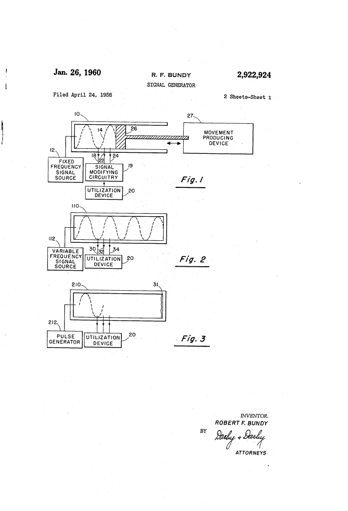
Bundy’s breakthrough was to use a transmission line (like a coaxial cable or waveguide) as the signal generator itself, effectively turning the physics of radio waves into a mechanical-free switching system.
By sending a signal down a line, Bundy created standing waves—patterns of high and low voltage that remain stationary. By then “moving” these waves, he could “tap” into the energy at specific points to trigger the display lines.
Three Ways to Move the Signal
Bundy outlined three distinct methods to ensure the triggering pulses moved across the display in sequence:
| Method | Mechanism | Benefit |
| Mechanical (Piston) | A conductive piston moves inside the line, physically shifting the wave pattern. | Simple conceptual design for slow displays. |
| Frequency Variation | The signal source changes its frequency, causing the wave peaks to naturally “slide” along the line. | No moving parts; allows for near-instant “reset” to the start of a frame. |
| Pulse Delay | A single pulse is sent down a “delay line,” energizing probes as it passes them. | Ideal for high-speed, non-standing wave applications. |
Technical Components
- Transmission Line (10): The “highway” for the signal, integrated directly into the display’s frame.
- Pickup Probes (18, 22, 24): Small elements positioned at peak wave points. In the final display, these “probes” are actually the ends of the vertical or horizontal display strips themselves.
- Movement Device (27): Either a mechanical actuator or a variable frequency oscillator that controls the timing of the scan.
- Modifying Circuitry: Pulse-shaping tools that ensure the signals are “sharp” enough to produce a crisp image on the screen.
Performance: Sharpness through Harmonics
One technical challenge was that radio wave peaks are often “rounded,” which could trigger two adjacent lines at once, causing a blurry image. Bundy proposed adding harmonic frequencies to the fundamental signal. These harmonics reinforce the main peak while canceling out the “shoulders” of the wave, resulting in extremely narrow, high-amplitude pulses for a high-definition (for 1960) presentation.
Impact on Display Design
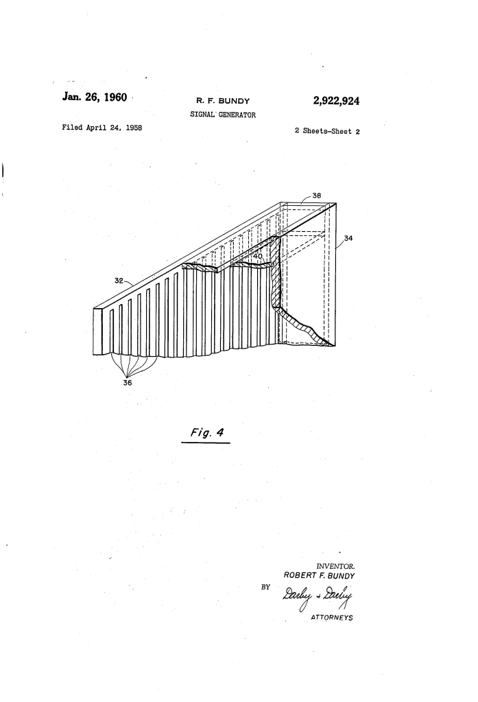
Bundy’s patent was visionary because it moved the “brains” of the display into the envelope (the housing) of the device:
- Unitary Structure: By building the transmission line onto a “shelf” inside the vacuum seal of the tube, the display and the signal generator became one single unit.
- Miniaturization: It eliminated the need for hundreds of external connections. The only external connection required was the master signal source.
- Signal Integrity: Shorter internal leads meant less signal loss and a much higher frequency response.
About the Inventor: Robert F. Bundy
Robert F. Bundy was an engineer at Allen B. Du Mont Laboratories, a company founded by the man who perfected the cathode-ray tube (CRT). Bundy’s work in Philadelphia contributed to the mid-century push to move television beyond the deep, heavy “box” and toward the “picture on the wall” concept that defines modern electronics.
Summary of Claims
The patent explicitly claims:
- A unitary structure where the triggering apparatus and the flat display device are contained within the same vacuum envelope.
- A transmission line formed by a shelf positioned between the walls of the display, serving as the axis for signal propagation.
- The use of conductive strips that serve dual purposes: acting as the pickup elements for the wave and as the light-producing electrodes for the display.
