
Shadow Box (1968)
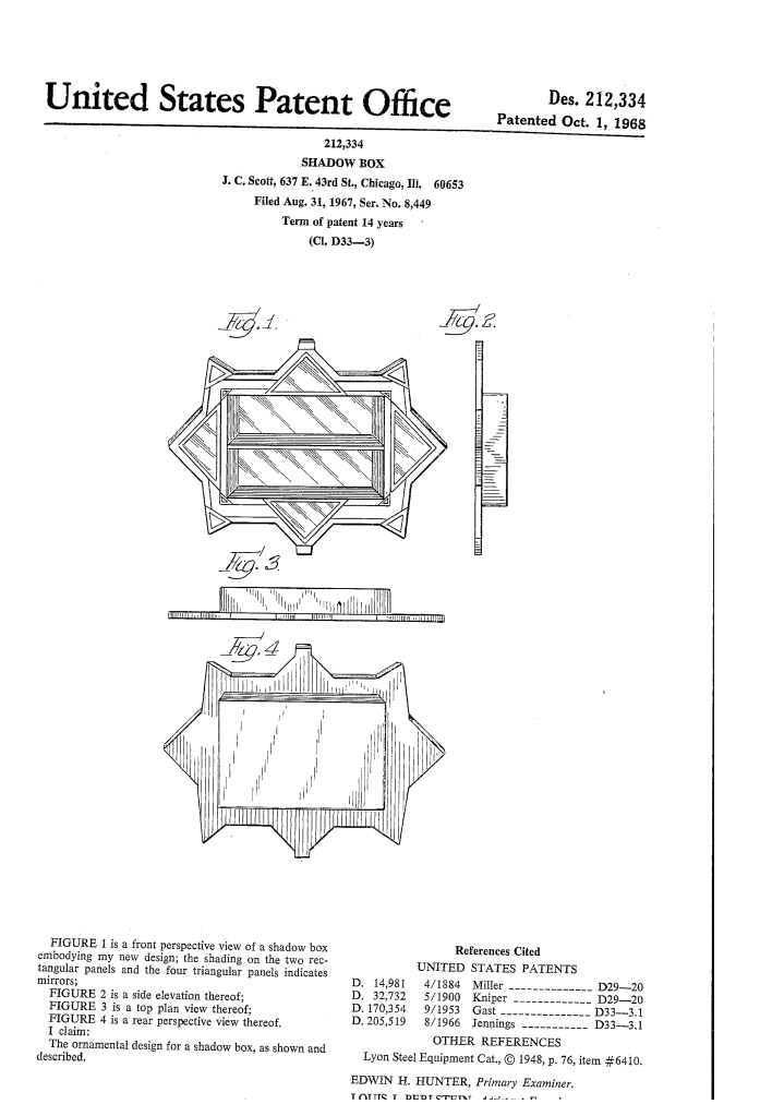
U.S. Patent No. Des. 212,334, granted on October 1, 1968, to J. C. Scott, establishes a distinctive ornamental design for an interior wall display shadow box. J. C. Scott, an inventor and designer residing at 637 East 43rd Street on the South Side of Chicago, Illinois, filed the design application in August 1967 for a 14-year patent term.
This creation addressed both functional display needs and modern aesthetic sensibilities in mid-century home furnishings: how to showcase small decorative objects, keepsakes, and art pieces while using integrated reflective geometry to multiply natural light and create an illusion of greater interior depth.
The Innovation: Faceted Mirror Geometry
Traditional mid-century shadow boxes typically featured flat rectangular wooden or metal compartments with simple flat backdrops. Scott’s breakthrough lies in the strategic arrangement of angled, multi-faceted mirrored planes within an open, tiered three-dimensional frame.
Why the Angled Mirrored Panels?
- Visual Depth: The interplay between two rectangular mirrors and four angled triangular mirrors breaks up flat wall surfaces, visually expanding compact living spaces.
- Multi-Angle Reflection: Objects placed on the display tiers are reflected from both rear and diagonal viewpoints, offering dynamic perspectives without requiring free-standing pedestals.
- Mid-Century Modern Aesthetic: The crisp, angular planes reflect the bold geometric decor trends popular in late-1960s interior architecture.
Key Design Elements
The ornamental design integrates structural shelving tiers with reflective facets:
| Component | Identifier | Aesthetic & Functional Role |
| Rectangular Mirrored Panels | Fig. 1 Shading | Forms the central reflective backings, grounding the main display tiers with direct front-to-back depth. |
| Triangular Mirrored Panels | Fig. 1 Shading (4 panels) | Set at complementary angles flanking the main tiers to capture side reflections and ambient room lighting. |
| Tiered Display Ledges | Figs. 1, 2, 3 | Provides open, structured horizontal planes for curating decorative items, art, or memorabilia. |
| Enclosing Shadow Frame | Figs. 1, 2, 4 | Delivers a clean architectural border that mounts securely flush against interior walls. |
Design Architecture and Perspectives
The patent details the aesthetic geometry across four distinct drafting views:
- Figure 1 (Front Perspective View): Shows the overall tiered display structure, detailing the placement of the two rectangular mirrored panels alongside four flanking triangular mirrors.
- Figure 2 (Side Elevation View): Illustrates the stepped profile and outer depth of the frame, showing how the tiers extend outward from the wall mount.
- Figure 3 (Top Plan View): Details the upper horizontal shelf boundary and the angular alignment of the internal structural supports.
- Figure 4 (Rear Perspective View): Displays the structural backing and flush-mounting framework designed to anchor the piece against the wall.
Historical and Cultural Context
Originating from Chicago’s historic Bronzeville and South Side cultural hub in the late 1960s, Scott’s patent reflects an era when independent urban designers and craftspeople actively contributed to modern consumer product design and decorative arts.
- The Shadow Box Boom: In post-war American interiors, shadow boxes evolved from military medal cases into essential living room centerpieces, often combining brass, wood, and mirrored glass.
- Urban Craftsmanship: Scott’s design stands out among independent municipal patents of the era, turning standard wall shelving into an elegant, sculptured focal point.
About the Designer: J. C. Scott
J. C. Scott was a Chicago-based designer and inventor based in Cook County, Illinois. Working during a pivotal period of expansion in American home goods manufacturing and interior styling, Scott secured federal design patent protection to commercialize unique decorative furnishings tailored for the modern home.
Summary of Claims
The patent explicitly claims:
- The ornamental design for a shadow box, substantially as shown and described in the accompanying perspective, elevation, and plan illustrations.
