
Self-Leveling Table (1898)
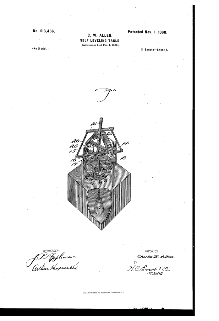
U.S. Patent No. 613,436, granted on November 1, 1898, to Charles Wm. Allen, describes a mechanical self-leveling table designed to maintain a flat, horizontal surface regardless of the motion or tilt of the floor underneath it. Charles Wm. Allen, an inventor residing in Option, Pennsylvania, engineered the apparatus specifically for maritime use aboard ships and passenger vessels.
At sea, the rolling and pitching of a ship frequently caused dishware, liquids, and dining utensils to slide off tables. Traditional marine tables often relied on rudimentary racks or fixed fiddles that merely corralled plates rather than preventing the movement itself. Allen’s invention solved this by decoupling the tabletop from the hull’s motion through a low-friction, multi-axis roller suspension driven by a heavy central pendulum.
The Core Design: The Hub-and-Track Gimbal System
Rather than using complex hydraulic systems or delicate electrical controls, Allen created a mechanical assembly centered around a cross-shaped spoked hub suspended over curved tracks.
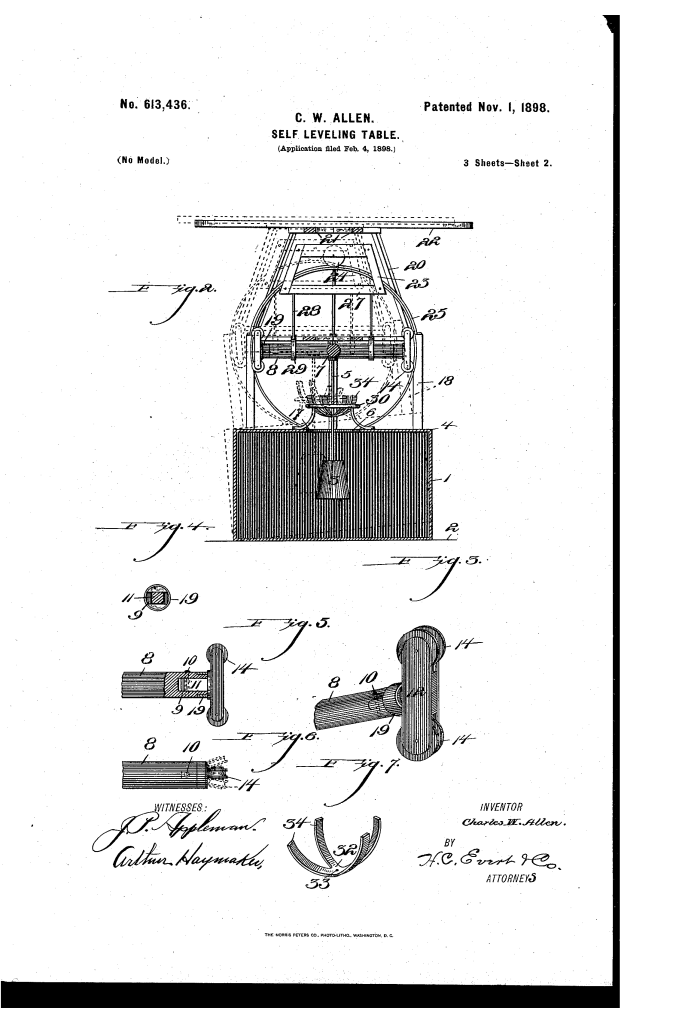
- The Hub and Spoke Assembly (7, 8, 14)At the center of the apparatus rests a cast hub (7) featuring four heavy spokes (8) extending outward at right angles.
- The outer end of each spoke terminates in a cutaway recess (9) forming two jaws reinforced with an outer metal band (19).
- Loosely pinned axles (11) mount vertical bars (12) that carry paired rollers or pulleys (14).
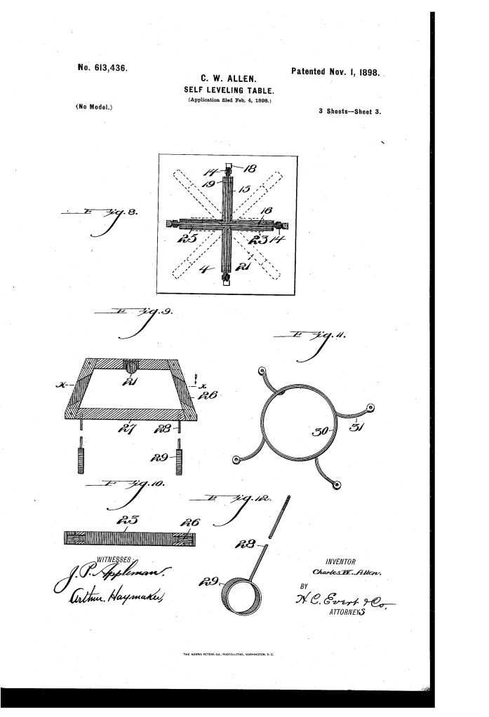
- These rollers ride directly upon intersecting circular overhead tracks (15, 16), which cross transversely at their apex and anchor into a base ring (17) on top of the supporting pedestal or deck floor.
- The Pendulum and Anti-Oscillation Guide (3, 5, 32)Suspended straight through the hub is a heavy vertical rod (5) carrying a counterweight or pendulum (3) inside an enclosed base casing (1).
- Gravity keeps the weighted pendulum pointing true toward the Earth’s center, generating the counter-torque required to keep the tabletop horizontal as the ship heels.
- To prevent the pendulum from swinging wildly out of control during rapid pitching, Allen added a threaded guide-plate (32) onto the central rod.
- The guide-plate features concavo-convex diverging fingers (34) that glide smoothly along an elevated circular track or guide-ring (30), dampening free oscillation while allowing responsive leveling.
How the Self-Leveling Assembly Operates
The apparatus converts the rotational and tilting movements of a vessel directly into rolling counter-movements:
| Stage | Action | Mechanical Purpose |
| 1. Vessel Pitch / Roll | The ship’s deck tilts, carrying the outer casing (1) and fixed arched tracks (15, 16) with it. | Introduces angular deflection to the base support. |
| 2. Pendulum Hold | The counterweight (3) on vertical rod (5) resists the tilt and remains perpendicular to the horizon. | Provides the physical anchor force for absolute equilibrium. |
| 3. Low-Friction Shift | The hub’s paired rollers (14) travel immediately along the tracks (15, 16). | Eliminates sticking or binding, enabling instantaneous mechanical response. |
| 4. Yoke Alignment | Overhead yoke (23) rolls along secondary track (25) while hangers (28) grasp the hub spokes. | Maintains alignment between the table frame (20) and the underlying mechanism. |
| 5. Surface Equilibrium | The table frame (20) and top (22) remain perfectly level without human adjustment. | Prevents dishes, glassware, and serving pieces from sliding or spilling. |
Key Mechanical Components
- Box / Casing (1): The enclosed base structure that acts as a secure protective housing for the counterweight beneath the floor or deck.
- Arched Tracks (15, 16): Dual curved guide rails crossing at 90 degrees at their peaks, supported by four rigid upright standards (18).
- Stabilizing Yoke (23): An intermediate frame housing an upper roller (24) that rides track 25; circular bands (29) loosely tether it to the hub’s horizontal spokes to eliminate binding.
- Concavo-Convex Guide Fingers (34): Curved spring-steel prongs radiating outward from the threaded collar (33) to absorb harmonic sway.
- Table Support Frame (20, 21): A framework mounted directly above the hub that forms the rigid seating surface for tabletop 22.
Historical and Maritime Context
During the late 19th century, the expansion of transatlantic passenger steamships spurred a wave of mechanical patents aimed at passenger comfort. Dining salons were central to luxury ocean travel, yet rough seas regularly disrupted meal service.
- Structural Isolation: Allen’s system was engineered to mount either as a freestanding cabinet piece (using base casing 1 and cover 4) or integrated directly into the ship’s architecture, dropping the pendulum rod through the deck planks into the cargo or service space below.
- Mechanical Simplicity: By pairing rolling-element contact with gravity actuation, the mechanism avoided the maintenance headaches of hydraulic seals or pneumatic dashpots, which routinely deteriorated in salty marine environments.
Summary of Claims
The patent explicitly claims:
- A self-leveling table structure utilizing upright standards supporting crossed circular tracks with a rolling spoked hub nested within.
- The combination of a gravity-actuated pendulum rod, an adjustable guide-plate, and an auxiliary circular guide-ring to prevent table oscillation.
- A floating yoke assembly fitted with hangers that loosely engage the hub spokes to preserve mechanical alignment across all operational angles.
