
Rotary Machine (1969)
U.S. Patent No. 3,456,594, granted on July 22, 1969, to Thomas L. Cosby (assigned to Seek, Incorporated), details an advanced reciprocating vane rotary mechanism configured to operate either as a fluid-driven motor or as a positive displacement pump.
This invention tackled a fundamental defect long found in conventional reciprocating vane rotary equipment: torque pulsation and operational roughness caused by fluctuating active vane surface area during rotation, combined with overly complex, jam-prone multi-piece vane assemblies. Cosby developed an elegant geometric balance between ramp geometry, chamber spacing, and vane count that guarantees a strictly constant active vane area throughout full rotation.
The Core Innovation: Constant Active Vane Area
In earlier vane-type rotary motors, driving torque constantly fluctuated under steady pressure because the exposed surface area of the vanes expanded and contracted unevenly as they rode up and down internal cam tracks.
Cosby eliminated this instability through a strict proportional layout:
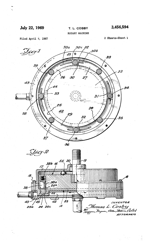
- Four Equal Chambers: The annular channel is segmented into four equal-length chambers by four ramp structures.
- 2:1 Vane-to-Chamber Ratio: The rotor carries exactly eight spring-loaded reciprocating vanes—precisely twice the number of chambers.
- 1/8th Circumference Geometry: Each ramp spans 1/8th of the channel circumference; the distance between adjacent ramps is 1/8th; and the angular spacing between adjacent vanes is 1/8th.
- Dedicated Active Zones: Vanes are completely sealed against the channel walls and bottom only when fully extended across the flat spans between ramps. Four vanes are always fully active simultaneously, maintaining perfectly uniform torque output and smooth displacement.
Key Mechanical Components
| Component | Function |
| Base Member (15) | The stationary stator featuring a circular channel (25) with straight side walls and a semi-circular bottom wall (25c). |
| Rotor Member (16) | The rotating disc-like plate holding reciprocating cylindrical vanes (32–39) within aligned guide bores (38a). |
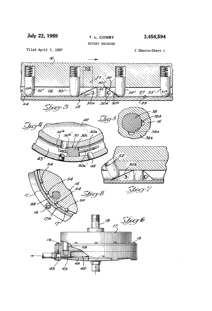
| Dividing Ramps (30–33) | Structures defining chambers (26–29). Each features a rising slope (30a), a descending slope (30b), and a full-width crest (30c) that seals against the rotor face. |
| Spring-Loaded Vanes (32–39) | Round cylindrical pins with rounded lower ends matching the channel floor contour; spring-urged downward to maintain contact. |
| Dual Concentric Manifolds (42, 43) | Inner manifold (42) directs inlet driving fluid into one end of each chamber via ports (44); outer annular manifold (43) exhausts fluid through ports (45). |
| Flexible Relief Plate (48) | A bottom plate sealed by a gasket (49) that elastically flexes outward during overpressure, shunting fluid directly from inlet to outlet to prevent mechanical destruction. |
Operational Cycle and Flow Dynamics
The machine executes continuous intake, drive, and exhaust cycles across each quadrant:
| Step | Action | Functional Purpose |
| 1. Fluid Admission | High-pressure fluid enters the inner manifold (42) and discharges through chamber inlet port (44). | Applies driving force against the back face of a fully extended vane (e.g., vane 32) exiting the ramp. |
| 2. Constant Drive | Pressurized fluid sweeps the vane across the uniform-depth channel between adjacent ramps. | Delivers constant displacement and uniform rotary torque with zero surface area variation. |
| 3. Fluid Bypassing | As the preceding vane climbs rising ramp (30a), narrow ramp clearances and cross-ports (30a’, 30b’) allow fluid to flow along both sides. | Prevents hydraulic locking and permits free exhaust through port (45) to the outer manifold (43). |
| 4. Pressure Equalization | Longitudinal vent grooves (38b) in the rotor bores vent fluid trapped behind retreating vanes. | Eliminates hydraulic entrapment behind the vanes so they retract without binding or excessive resistance. |
Engineering Refinements and Anti-Jam Architecture
Cosby engineered several specific mechanical details to overcome friction and lateral binding:
- Asymmetrical Ramp Slopes: The descending ramp portion is steeper and shorter than the rising slope, minimizing overall ramp footprint without creating excessive lateral side-thrust on the extending vanes.
- Normal Vane Alignment: In an alternative configuration, vanes are mounted at an angle perpendicular to the slope of the rising ramp, virtually eliminating lateral tipping forces.
- Integral Bearing Action: The round vanes function as sliding/rolling elements between stator and rotor; auxiliary peripheral ball or roller bearings (54) and thrust ball bearings (55) absorb external axial and radial loads.
- Dual Functionality: Operated as a motor, the unit runs on fluids such as SAE 20 lubricating oil under continuous pressure; driven externally via shaft (19), it acts as a smooth, multi-chamber fluid pump.
Summary of Claims
The patent explicitly claims:
- An annular channel split into equal-length chambers by ramps having rising, descending, and high-point sections, paired with twice as many equally spaced reciprocating vanes as chambers.
- Sizing where total ramp length, ramp-to-ramp gap, and inter-vane distance are each substantially equal to achieve a constant active vane area.
- Cylindrical reciprocating vanes having rounded ends matching a complementary curved channel bottom.
- Concentric inner and outer manifolds connected to opposing chamber ports, sealed by an overpressure-relieving flexible plate.
- Vent passages positioned along the rotor vane bores to relieve fluid pressure behind the reciprocating vanes.
