
Rotary Compressor, Frederick M. Jones (1950)
Patented on April 18, 1950, this invention (U.S. Patent No. 2,504,841) represents a masterclass in compact mechanical engineering by Frederick M. Jones. At the time, refrigeration units for trucks and trains required powerful compressors, but standard piston-based models were bulky, heavy, and prone to vibration.
Jones developed a Two-Stage Rotary Compressor that achieved higher pressure and greater efficiency in a fraction of the space. By using the exterior of a rotor for the first stage of compression and the interior for the second stage, he essentially packed two machines into one housing.
The “Why”
In the 1940s, “mobile” refrigeration was the frontier. For a cooling unit to work on a truck, it needed to be:
- Compact: It had to fit in a small compartment on the front of a trailer.
- Efficient: It needed to evacuate refrigerant vapor quickly from an evaporator, even when the pressure was lower than the surrounding air.
- Cool: High-speed compressors generate massive heat; Jones needed a way to shed that heat to prevent the unit from seizing.
The Solution: A “Rotor-within-a-Cylinder” design where centrifugal force drives the compression, and a stationary “Core” acts as a sophisticated traffic controller for the gas.
Inventor Section: Frederick M. Jones
Jones’s design philosophy for this compressor was Rotational Symmetry and Thermal Integration. He integrated a cooling fan directly onto the drive shaft and used the structural ribs of the casing as a heat exchanger. He famously sought to eliminate friction; by making both the rotor and the outer cylinder rotate together, he minimized the “sliding” friction that usually wears down rotary vanes.
Key Systems Section
1. The Two-Stage Compression Cycle
This is the heart of the patent. The gas is squeezed twice in one full rotation.
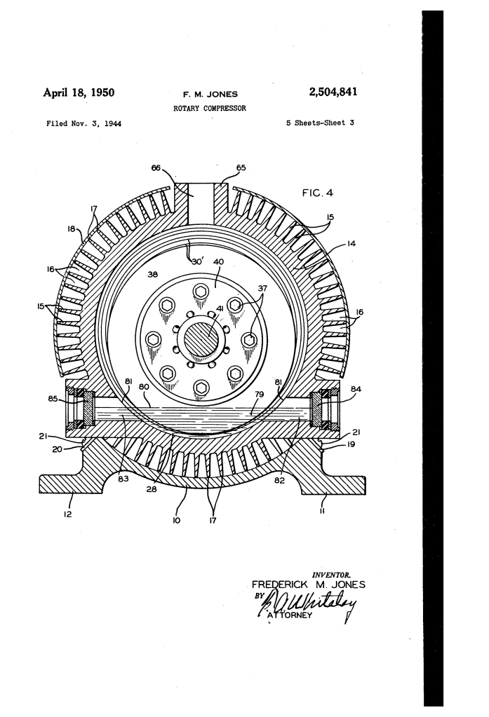
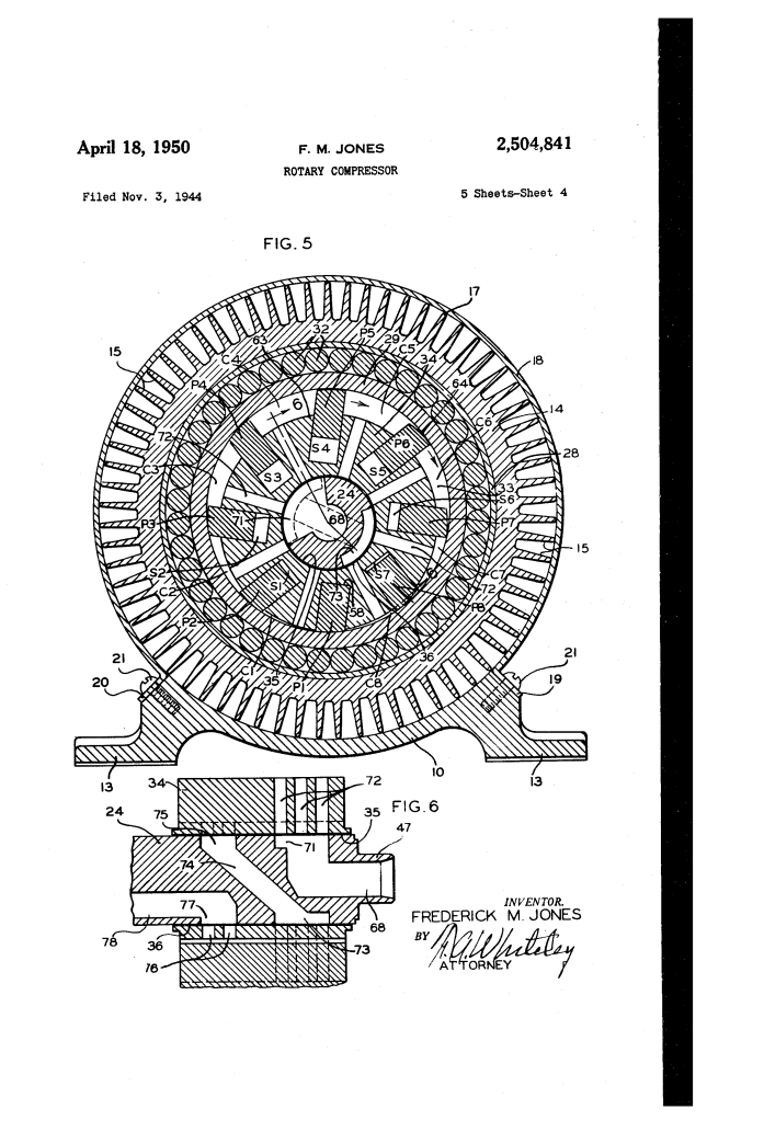
- Stage 1 (Exterior): Gas enters a crescent-shaped chamber (63) between the rotor and the outer cylinder. As the rotor turns, the space shrinks, providing the first level of pressure.
- Stage 2 (Interior): The partially compressed gas is pushed through ports into the slots behind the pistons (P1-P8). As the rotor’s eccentric path pushes the pistons back into their slots, the gas is squeezed a second time against the stationary center core.
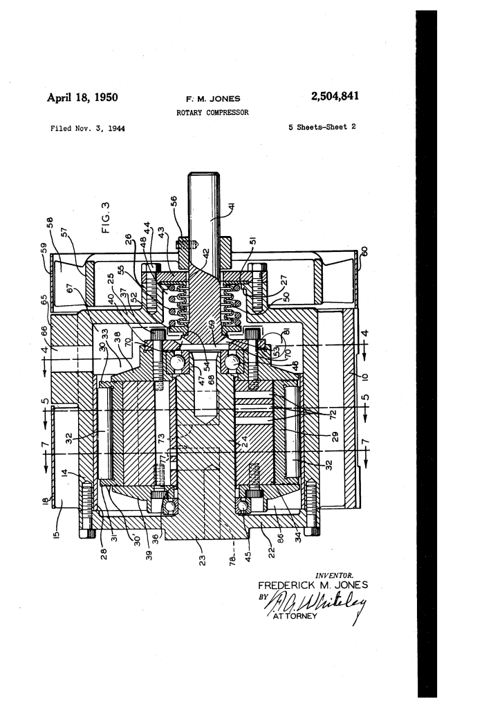
2. The Stationary Bearing Post (The “Traffic Controller”)
The Bearing Post (24) is a non-moving core that sits in the center of the spinning rotor.
- Passageways: It contains a complex system of bores (chambers 68, 73, 75) that align with ports in the spinning rotor at exactly the right micro-second.
- Automatic Valving: There are no traditional flapping valves. The rotation of the rotor itself acts as the valve—opening and closing the connection to the intake and exhaust as the ports sweep past the openings in the stationary post.
3. Integrated Cooling & Friction Reduction
- Rotating Cylinder (29): Unlike most compressors where vanes scrape against a still wall, Jones’s outer cylinder rotates with the rotor on roller bearings. This dramatically reduces wear.
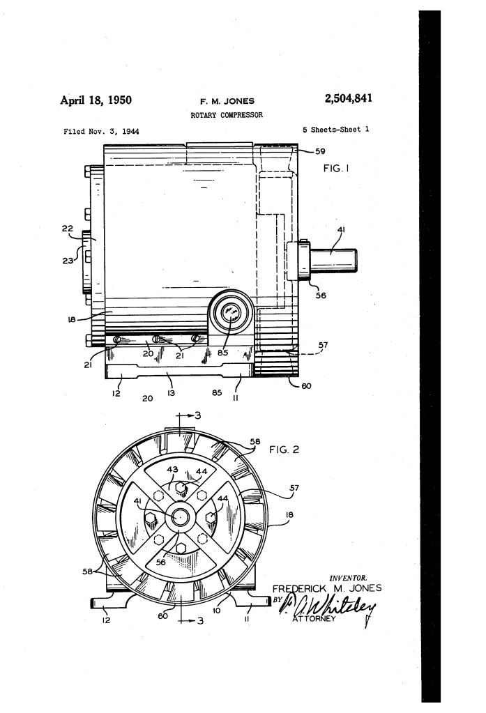
- Heat Dissipation: The casing features longitudinal ribs (16). A fan (57) mounted directly on the drive shaft blows air through these ribs, essentially turning the entire compressor body into a radiator.
How the Gas Travels (The “Jones Loop”)
| Step | Location | Action |
| 1. Intake | Central Bore (68) | Low-pressure vapor enters from the evaporator. |
| 2. Stage 1 | Crescent Chamber (63) | Gas is squeezed between the rotor and the rotating outer shell. |
| 3. Transfer | Transverse Passage (74) | The mid-pressure gas is “looped” from the outside to the inside of the rotor. |
| 4. Stage 2 | Piston Slots (S1-S8) | Pistons are forced inward, crushing the gas against the stationary core. |
| 5. Exhaust | Exhaust Passage (78) | High-pressure gas is sent to the condenser to be turned back into liquid. |
Technical Components
| Part Number | Component | Function |
| 24 | Bearing Post | The stationary core that manages gas flow between stages. |
| 33 | Rotor | The spinning heart of the machine that carries the pistons. |
| 29 | Cylinder | Rotates with the rotor to reduce friction and wear. |
| P1-P8 | Pistons | Act as sliding vanes to seal the compression chambers. |
| 57 | Blower Fan | Provides constant air-cooling to the finned casing. |
Significance
The 1950 Rotary Compressor patent was the “engine” that powered the expansion of Thermo King:
- Unmatched Power-to-Weight: It allowed for a smaller engine to drive the cooling system, saving fuel and increasing cargo space.
- Durability: The “dual-rotation” design (cylinder and rotor moving together) meant the units could run for thousands of hours with minimal maintenance.
- Vacuum Efficiency: It was exceptionally good at “pulling a vacuum,” ensuring that the refrigeration cycle could start quickly even in hot weather.
Final Insight: Jones’s compressor wasn’t just a part; it was a self-contained thermal management system. By using the stationary core to move gas from the exterior to the interior, he solved the problem of “volumetric efficiency”—getting the absolute most out of every cubic inch of the machine.
