
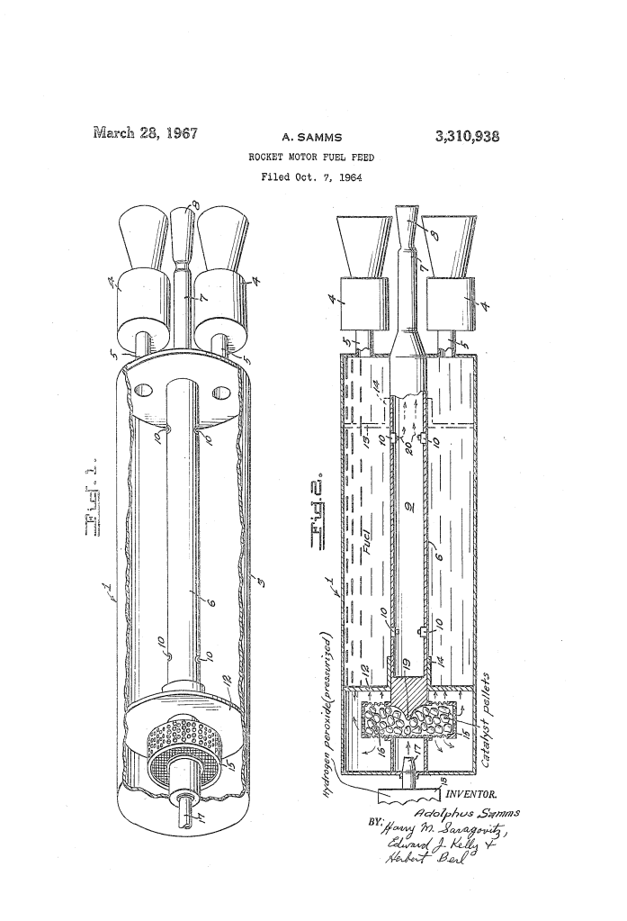
Rocket Motor Fuel Feed (1967)
U.S. Patent No. 3,310,938, granted on March 28, 1967, to Adolphus Samms, describes an internal steam-pressurization mechanism designed to feed liquid propellants directly into rocket engines without turbopumps. Samms, an inventor based at the Yuma Proving Ground in Yuma, Arizona, addressed a major engineering hurdle in mid-century aerospace: the weight, complexity, and mechanical vulnerability of liquid-fuel delivery systems.
Conventional liquid-propellant rockets relied on heavy turbopumps, separate drive turbines, and reinforced fuel tanks to deliver fuel and oxidizer to the combustion chamber under high pressure. These systems added significant parasitic mass and introduced numerous points of mechanical failure. Samms developed an in-tank steam generator and sliding pressure-plate system that eliminates pumps entirely while stabilizing liquid propellants during flight.
The Core Design: In-Tank Catalytic Steam Pressurization
The central breakthrough is the elimination of external pumps through an integrated, in-tank catalytic steam generator that drives an internal piston plate along a central hollow shaft.
- The Catalytic Steam Generator (15, 16)Mounted directly on the axial shaft within the tank compression space is a wire or perforated metal cage filled with catalyst pellets. When pressurized hydrogen peroxide from an auxiliary supply is sprayed through internal nozzles onto the catalyst bed, it decomposes rapidly into high-pressure steam and oxygen gas.
- The Sliding Pressure Plate (12, 14)A movable barrier plate fitted with an integral collar slides axially along the main shaft. Piston rings or fluid-tight packings seal the perimeter against the inner tank wall and shaft. As the expanding steam impinges on the plate, it drives it downward, forcing the underlying liquid propellant smoothly into the feed lines connected to the rocket motors.
- Pressure Relief and Overpressure Exhaust (6, 9, 10)The central shaft serves a dual mechanical and pneumatic purpose. Beyond guiding the pressure plate, it houses an internal exhaust passageway fitted with relief valves. If steam pressure exceeds operational thresholds, or once the fuel is fully exhausted, excess gas vents into the hollow shaft and exhausts rearward through an aft nozzle, preventing tank overpressurization or structural rupture.
How the Apparatus Functions
The system operates in a direct, pressure-driven sequence upon rocket ignition:
| Step | Action | Operational Purpose |
| 1. Launch Command | Firing switch opens solenoid valves to release pressurized hydrogen peroxide from auxiliary tank 18. | Initiates the gas-generation sequence on demand. |
| 2. Catalytic Injection | Hydrogen peroxide enters hollow shaft 6, deflects off baffle 19, and sprays via nozzle 17 onto catalyst pellets 16. | Ensures wide dispersion and rapid, complete decomposition into high-temperature steam. |
| 3. Positive Displacement | Generated steam fills the compression zone behind plate 12, driving it downward along the central shaft. | Forces fuel or oxidizer through discharge lines 5 into rocket motors 4 under constant pressure. |
| 4. Overpressure Relief | Excess steam triggers relief valves 10, venting into central passageway 9 and out through rear nozzle 8. | Protects tank 3 from catastrophic burst pressures during flight and at fuel burnout. |
Technical Components
- Fuel/Oxidizer Tank (3): Cylindrical storage vessel containing liquid fuel or oxidizer, divided dynamically into a fuel area and a compression area by the moving plate.
- Central Hollow Shaft (6): Structural axle extending through the length of the tank and terminating in rear nozzle 8, housing passageway 9 and relief valves 10.
- Piston Plate and Collar (12, 14): Sliding pressure partition separating steam and propellant while acting as an active barrier against propellant movement.
- Catalyst Cage and Pellets (15, 16): Perforated housing containing catalytic material to drive the exothermic breakdown of hydrogen peroxide.
- Internal Baffle (19): Deflector plate within the hollow shaft positioned to atomize and direct hydrogen peroxide evenly over the catalyst bed.
Aerospace and Flight Impact
Adolphus Samms assigned the patent royalty-free for governmental use, offering concrete benefits for Department of Defense and aerospace rocket engineering:
- Weight and Turbopump Elimination: By removing mechanical fuel pumps, drive turbines, and their auxiliary power assemblies, the design stripped massive weight from the propulsion section.
- Active Anti-Slosh Control: Liquid sloshing inside propellant tanks alters a rocket’s center of mass and creates guidance instability. The tight-fitting pressure plate physically rests atop the fluid column, suppressing sloshing entirely without requiring heavy internal anti-slosh baffles.
- System Simplicity: The self-contained pneumatic architecture reduced the number of moving mechanical components, improving reliability during launch sequences.
About the Inventor: Adolphus Samms
Adolphus Samms was an African American inventor who made key contributions to missile engineering, rocketry, and military ordnance while stationed at the U.S. Army’s Yuma Proving Ground in Arizona during the 1960s. Samms held multiple patents in rocketry hardware, including designs for multi-stage rocket systems, propellant injectors, and air-breathing propulsion mechanisms, contributing practical mechanical innovations to the United States space and defense programs during the Space Race.
Summary of Claims
The patent explicitly claims:
- A rocket motor fuel feed combining a fuel tank in fluid communication with a rocket motor, an axial hollow shaft with an internal passageway and aft nozzle, a shaft-mounted steam generator, a sliding pressure plate, and relief valves venting into the shaft.
- A tank divided into a propellant zone and a compression zone by a sliding plate mounted on a central shaft, pressurized by an in-tank steam generator positioned behind the plate to feed propellant to the engine.
- An overpressure relief system where relief valves in the central shaft route excess steam through the rear exhaust nozzle.
