
Rocket Engine Pump Feed System (1961)
U.S. Patent No. 3,000,179, granted on September 19, 1961, to Alphonso Samms, describes an innovative fuel feed system for rocket engines. At the time of this patent, many rocket systems relied on heavy, high-pressure tanks to force fuel into the combustion chambers. Samms’ design aimed to replace that weight and complexity with a lightweight, turbine-driven pump system that utilizes the engine’s own exhaust gases to sustain flight.
Core Components of the System
The Samms system is built around a centralized power loop that recycles energy from the combustion process:
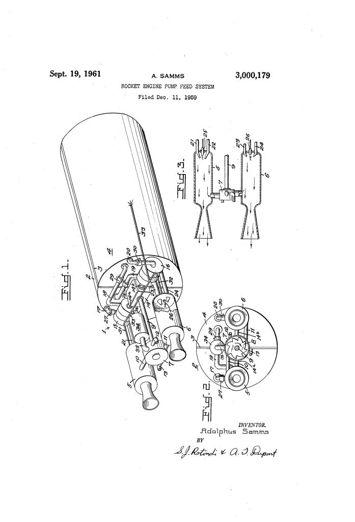
- Propellant Tanks: A single cylindrical tank is split by a divider wall into two separate compartments: one for liquid fuel and one for an oxidizer.
- Dual Combustion Chambers: The engine features two parallel combustion chambers (5 and 6) where the propellants are ignited by electric glow plugs.
- The Turbine Assembly: A bucket-type turbine wheel (8) is mounted between the combustion chambers. It is connected to the chambers via pipelines (10 and 11) that bleed off high-pressure combustion gases to spin the turbine.
- Centrifugal Pumps: A gear transmission box (14) translates the turbine’s rotation into the movement of two centrifugal pumps (15 and 16). These pumps draw the fuel and oxidizer from the tanks and force them into the combustion chambers.
The Operation Cycle: From Kickstart to Exhaustion
The Samms system is designed to be self-sustaining once it is initiated. The process follows these steps:
- Booster Initiation: To start the engine, a small solid propellant booster rocket (34) is fired. Its exhaust gases impinge on the turbine wheel, spinning the shaft.
- Pump Priming: As the turbine spins, it drives the centrifugal pumps via the gear box. These pumps pull the fuel and oxidizer through a network of pipes protected by check valves (to prevent backflow).
- Self-Sustained Combustion: The propellants are sprayed into the chambers and ignited by glow plugs. Once combustion is established, a portion of the resulting high-pressure gas is diverted back to the turbine.
- Feedback Loop: This redirected gas keeps the turbine spinning, which keeps the pumps running, ensuring a continuous supply of propellant until the tanks are completely empty.
Key Advantages of the Samms Design
By utilizing a turbine powered by combustion gases (a concept similar to a modern turbopump), Samms achieved several engineering goals:
| Feature | Old High-Pressure Systems | Samms Pump Feed System |
| Weight | Heavy (requires thick-walled, high-pressure tanks) | Light (uses low-pressure tanks and small pumps) |
| Complexity | High (complex pressure regulators) | Simple (integrated turbine-pump loop) |
| Duration | Limited by pressure decay | Functions until fuel is physically exhausted |
| Safety | High risk of tank rupture | Lower risk due to lower tank pressures |
Technical Summary
- Startup Mechanism: Electric ignition of a solid booster rocket.
- Transmission: Gearbox connecting a single turbine shaft to dual pump axles.
- Valving: Check valves to prevent propellant from leaking or flowing backward into the tanks when the system is inactive.
