

Rocket Catapult (1969)
U.S. Patent No. 3,447,766, granted on June 3, 1969, to Hugh D. MacDonald, Jr. et al., describes an emergency man-seat rocket catapult designed for high-speed emergency aircrew escape.
This specific invention solved a severe life-safety engineering dilemma in military aviation: how to sequence the initial mechanical catapult stroke and the subsequent rocket sustainer burn cleanly, without relying on fragile unlatching linkages, complex flow control valves, or moving metal components that could jam or malfunction under extreme gravitational and aerodynamic stresses.
The Innovation: The “Ablative Inhibitor” Timing Barrier
Traditional rocket catapults relied on complex mechanical interlocks, gas valves, or separate pyrotechnic cartridges to hand off propulsion from the preliminary booster tube stroke to the free-flight rocket burn. These mechanisms added dead weight and introduced critical single points of failure.
MacDonald and his team eliminated mechanical timing mechanisms by turning to solid-propellant chemical kinetics. By coating every surface of the main tubular rocket grain—especially its inner bore—with a chemically tailored ablative inhibitor lacquer, they used the combustion wash of an upstream forward gas generator to regulate the exact millisecond of main rocket ignition.
Why the Inhibitor-Coated Core?
Separation of Phases: The gas generator output first pressurizes the launch tube to stroke the rocket tube upward like a piston, keeping the high-thrust main propellant shielded until the seat clears the cockpit sill.
Valveless Timing Control: The flowing generator gas gradually erodes and consumes the internal inhibitor coating during the catapult stroke, exposing the high-rate double-base rocket propellant at the precise moment the assembly departs the launch tube.
Physiological G-Force Tuning: By varying the chemistry and combustion contribution of the inhibitor layer, the propulsion engineers smoothed out the initial pressure spike to keep seat acceleration within human physiological tolerances.
Key System Components
The apparatus integrates catapult boost, automatic unlatching, and free-flight rocket sustainment into a concentric assembly:
| Component | Function |
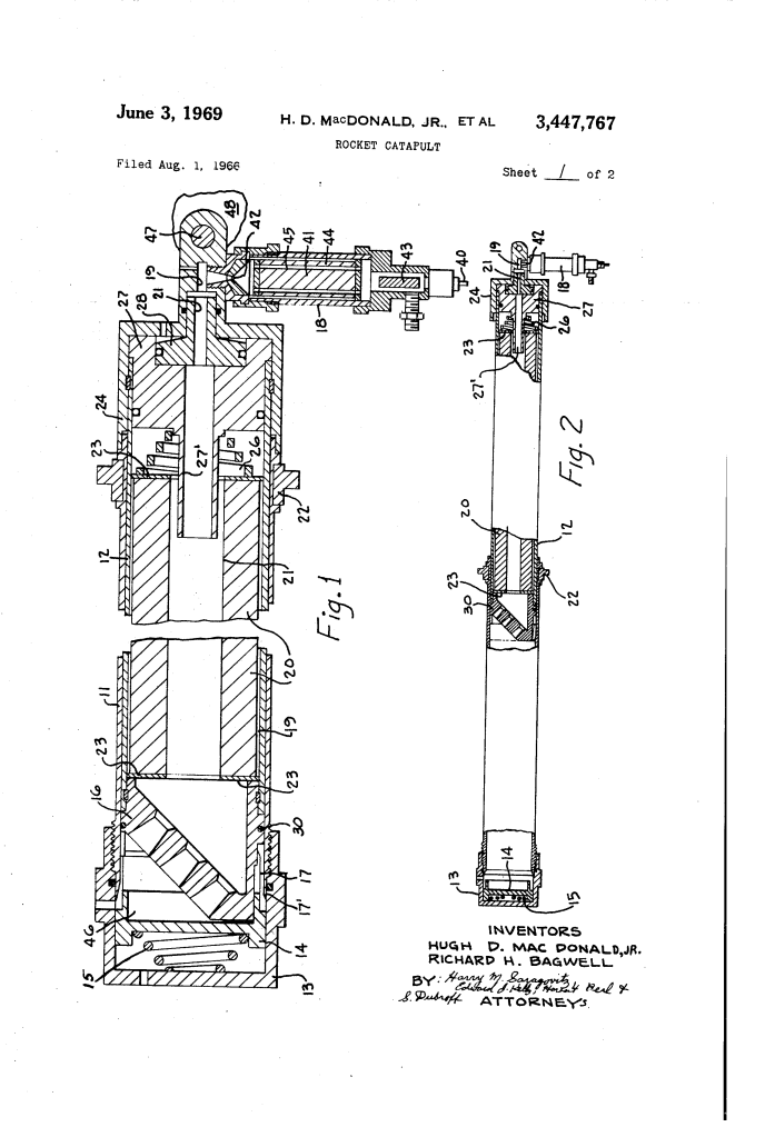
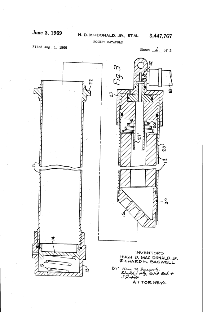
| Launching Tube (11) | Airframe-mounted exterior guide cylinder anchored via rear breech member 13 and forward trunnions 22. |
| Rocket Motor Tube (12) | Telescoping cylinder pinned to aircraft seat member 48 by trunnion fitting 47; houses the primary sustainer propellant. |
| Gas Generator (18) | Forward-mounted housing containing perforated solid propellant grain 41; ignited by electric element 40 to supply initial catapult gas. |
| Releasable Latching Fingers (17) | Spring-biased mechanical detents seated against launch tube lip 17′; normally lock the assembly against forward launch travel. |
| Movable Can (14) & Spring (15) | Pressure-actuated collar biased by spring 15; forced rearward by initial generator gas pressure to unlock latching fingers 17. |
| Main Tubular Propellant (20) | High-energy double-base grain biased against nozzle 16 by spring 26; powers the free-flight climb away from the aircraft. |
| Propellant Inner Coating (21) | Calibrated chemical barrier applied to the internal grain bore; resists ignition until consumed by hot exhaust gases. |
How the Catapult Functions
The ejection sequence executes a continuous thermodynamic transition across three distinct mechanical stages:
| Step | Action | Operational Purpose |
| 1. Initiation | Electric element 40 fires igniter 43, burning multi-perforated propellant 41 in forward gas generator 18. | Rapidly generates high-pressure gas without igniting the main rocket grain. |
| 2. Pressure Unlatching | Gas flows through channels 19, 21, tube conduit 27′, and nozzle 16 into chamber 46, forcing can 14 rearward against spring 15. | Withdraws the backing support behind latch fingers 17, freeing the rocket tube to move forward. |
| 3. Catapult Stroke | Expanding gases trapped in launch tube 11 push against rear nozzle 16 and O-ring seal 30, driving the seat assembly upward as a piston. | Accelerates the pilot up the escape rails on a controlled, survivable force-time curve. |
| 4. Sustainer Transition | As nozzle 16 exits launch tube 11, the hot gas wash completely burns through inhibitor coating 21. | Instantly ignites main grain 20 to provide sustained rocket thrust high above the tail structure. |
Performance: Controlled Combustion Kinetics
The patent details precise propellant burning rates and chemical inhibitor formulations to prevent explosive over-pressurization while ensuring reliable transition timing.
Main Rocket Propellant Dynamics:
- Composition: Double-base solid propellant grain configured with star, rosette, or wagon-wheel cross-sections to maximize interior burning surface area.
- Burning Rate: Designed for 0.4 inches per second at 1,000 psi, accelerating to 1.2 inches per second at the operational chamber pressure of 3,000 psi.
Inhibitor Coating Systems:
- Non-Propulsive Barrier: Pure ethyl cellulose deposited from a 5% solution in lacquer (31% to 35% ethyl lactate by volume, balanced with normal butyl acetate). Serves as a neutral, sacrificial thermal delay.
- Slow-Burn Contributive Barrier (X9): Deposited from a 10% solution of X9 propellant in ethyl lactate/butyl acetate lacquer; provides a burning rate of approximately 0.1 inches per second at 1,000 psi, contributing working gas to the catapult stroke while delaying main grain light-off.
- Moderate-Burn Contributive Barrier (X16): Formulated with X16 propellant in lacquer; burns at approximately 0.2 inches per second at 1,000 psi for applications requiring higher intermediate stroke energy.
Historical and Aerospace Impact
MacDonald’s rocket catapult represented a pivotal refinement in supersonic escape systems during the late 1960s:
- Component Simplification: By utilizing the propellant coating itself as the ignition timing device, the design removed heavy shuttle valves, mechanical shear pins, and secondary mechanical tripwires.
- Elimination of Acceleration Shock: Earlier purely pyrotechnic catapults delivered violent punch strokes that caused spinal compression injuries. MacDonald’s integrated gas-generator flow smoothed peak acceleration into a continuous thrust profile.
- Operational Reliability: The solid-propellant arrangement minimized sensitivity to storage temperatures and ensured that the sustainer phase could never ignite prematurely inside the cockpit or fail to ignite after rail departure.
About the Inventor: Hugh D. MacDonald, Jr. et al.
Hugh D. MacDonald, Jr. and his co-inventors were ordnance and aerospace propulsion specialists working on aircrew life-support systems. Their mechanical and chemical patents during the Vietnam War era contributed to emergency egress systems deployed across United States military aircraft, establishing standards for seat stabilization and solid-propellant timing control.
Summary of Claims
The patent explicitly claims:
- An aircraft man-seat ejection unit comprising a fixed launching tube, a telescoping rocket tube carrying seat-attachment fittings, and releasable latching fingers normally restraining forward motion.
- A forward-mounted gas generator housing containing an apertured solid propellant grain in fluid communication through a central conduit with the rear exhaust nozzle.
- An elongated tubular rocket propellant grain whose outer, end, and internal surfaces are covered with an inhibitor coating to delay sustainer ignition.
- An internal inhibitor coating comprising ethyl cellulose dissolved in ethyl lactate and butyl acetate lacquer, or alternatively a contributive propellant coating burning at 0.1 to 0.2 inches per second at 1,000 psi.
