
Remote Control Proportional Movement Motor | David N. Crosthwait, Jr. | Patent No. 2,007,240
The patent by David N. Crosthwait, Jr. of Marshalltown, Iowa, describes a Remote Control Proportional Movement Motor (Patent No. 2,007,240), issued on July 9, 1935. This invention is a highly precise electrical control system utilizing a reversible induction motor and a dual-resistance balancing bridge to achieve exact mechanical positioning from a distance.
The “Why”
In the early 1930s, industrial heating and ventilation systems required constant adjustment of valves and dampers based on fluctuating temperatures. Existing systems were often binary (fully open or fully closed) or required manual intervention. Crosthwait identified the “pain point” of imprecise, non-automated thermal regulation, seeking to create a device that could move a valve to a position proportionate to a temperature change—essentially inventing a mechanical precursor to modern automated climate control.
The Inventor: David N. Crosthwait, Jr.
David Crosthwait was a titan of heat transfer and thermodynamics. As a Black engineer and polymath rising to the rank of Director of Research at C.A. Dunham Co., his engineering philosophy centered on Systemic Equilibrium. In an era where industrial automation was in its infancy, Crosthwait’s work provided the mathematical and mechanical backbone for large-scale HVAC systems, including those later used in Rockefeller Center. His patents are masterclasses in using electrical signals to mimic human-like adjustments.
Key Systems Section
Opposed Shading Coil Logic
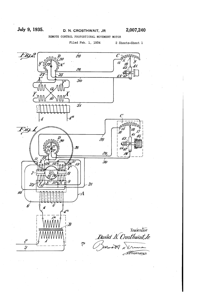
- Bidirectional Stator: The motor ($A$) features a squirrel-cage rotor ($E$) and two sets of “shading coils” ($X$ and $Y$).
- Flux Balancing: Coils $X$ induce clockwise torque, while coils $Y$ induce counter-clockwise torque. When the current in both is equal ($I_x = I_y$), the magnetic fluxes cancel out, and the rotor remains stationary.
The Proportional Bridge (Potentiometric Control)
- Master Resistance ($C$): Located at the remote site (e.g., a thermostat), a movable contact ($18$) divides the resistance into two parts ($x$ and $y$).
- Balancing Resistance ($D$): Located at the motor, this resistance ($r$ and $y’$) is physically geared to the motor’s shaft.
- Self-Correcting Loop: When the remote contact $C$ moves, it creates an electrical “unbalance.” The motor turns to move a valve, and simultaneously moves contact $23$ on the balancing resistance until the bridge is re-equalized ($x+r = y+y’$), at which point the motor stops.
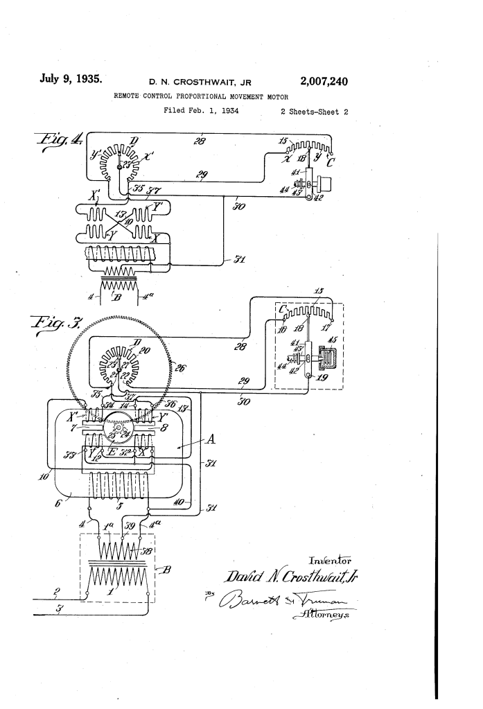
Transformer “Boosting” Circuit
- Secondary Reinforcement: In his second embodiment (Figs. 3 & 4), Crosthwait introduced a “tap” ($38$) from the transformer’s secondary coil.
- Sensitivity Enhancement: This tap feeds a small amount of supplemental current directly into the shading coil circuits, “boosting” the torque and making the motor responsive to even the slightest movement of the remote contact.
Shutterstock Explore
(Visualization: A Wheatstone bridge circuit diagram showing how a middle galvanometer—or in this case, a motor—reacts to resistance changes.)
Comparison: Standard 1930s Controls vs. Crosthwait’s Innovation
| Feature | Standard “On-Off” Controls | Crosthwait’s Proportional Motor |
| Movement Type | Binary (Open/Closed). | Incremental (Proportional to signal). |
| Control Signal | Direct manual or simple switch. | Remote resistance bridge (Potentiometer). |
| Feedback Loop | None; requires visual confirmation. | Automatic internal balancing. |
| Application | Basic machinery. | Complex HVAC and fluid dynamics. |
Significance
- Foundational HVAC Tech: This system is the direct ancestor of the modern modulating actuator used in every commercial building today.
- Precision Engineering: Crosthwait’s use of a “squirrel cage” rotor provided a rugged, brushless solution that minimized maintenance in harsh industrial environments.
- Automation Pioneer: By creating a “self-stopping” motor based on electrical balance, he helped transition the industry from manual labor to autonomous mechanical systems.
