
⚡ Relay-Instrument (Granville T. Woods, No. 364,619)
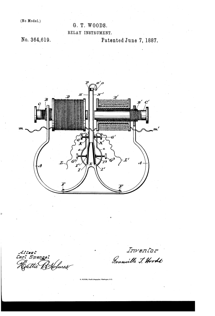
The patent by Granville T. Woods of Cincinnati, Ohio, describes a Relay-Instrument (Patent No. 364,619, 1887). This invention is a highly sensitive and durable electromagnetic relay designed for use in telegraphy. It was specifically engineered to support Woods’s broader system of inductive telegraphy, which allowed for communication between moving trains and stationary stations—a feat that required instruments capable of maintaining precision despite the heavy vibrations and shocks of a traveling locomotive.
Inventor Background: Granville T. Woods
Granville T. Woods (1856–1910), often called the “Black Edison,” was one of the most prolific African American inventors in history, holding over 50 patents. His work revolutionized the railroad and telegraph industries. The 1887 relay patent was a critical component of his Synchronous Multiplex Railway Telegraph, which saved countless lives by allowing train dispatchers to communicate with moving trains to prevent collisions. Woods’s engineering was characterized by a focus on “sensitiveness of action” and mechanical stability, allowing his devices to function in harsh industrial environments where others failed.
Key Mechanical Components & Functions
The relay uses a balanced magnetic field to control a local circuit with extreme precision.
1. The U-Shaped Magnet and Polar Extensions (A, B)
- The Frame: The base of the instrument is a U-shaped magnet (A).
- Hollow Extensions (B): Mounted horizontally in the ends of the magnet are hollow polar extensions (B).
- Adjustability: These extensions are threaded, allowing them to be moved closer or further apart to fine-tune the magnetic gap.
2. The Electro-Magnet Cores (C, D)
- The Cores (C): Inside the hollow extensions are the cores (C) of the electro-magnets.
- The Helices (D): These are the wire coils (helices) connected to the main telegraph line (m).
- Magnetic Logic: Woods wound the coils so that the ends of the magnets facing each other exhibit the same sign of magnetism (e.g., both North poles).
3. The Vibratory Armatures (H, H) (Key Innovation)
Instead of a single heavy swinging arm, Woods used two upright, flexible soft-iron armatures (H, H).
- Flexion vs. Pivot: These armatures are clamped at the bottom to a central stand (E) but are free to move at the top through flexion (bending) rather than a friction-prone mechanical pivot.
- Sensitivity: This design makes the relay incredibly sensitive to even the weakest electrical currents, as there is no pivot friction to overcome.
4. The Contact System (O, P)
- Contact Buttons (O, O): One armature is longer than the other and bends around to face its partner. They are tipped with contact buttons.
- Insulating Block (P): A back-stop made of insulating material (P) keeps the armatures apart when the circuit is at rest.
Operation: Closing the Local Circuit
The relay acts as a bridge between a weak long-distance signal and a strong local battery.
- At Rest: The resiliency (springiness) of the armatures holds them against the insulating block (P). The local circuit (L, L) is open.
- Signal Received: When a pulse of electricity travels through the main line (m), the electro-magnets (C, C) are energized.
- Magnetic Attraction: Because the magnets now exhibit a strong magnetic pull, they draw the flexible armatures (H, H) apart.
- Circuit Closed: This movement brings the contacts (O, O) together, closing the local circuit and triggering the telegraph sounder or recorder.
- Signal Ends: When the current stops, the armatures spring back to their original positions, reopening the circuit.
Improvements Over Standard Relays
| Feature | Standard 1880s Relays | Woods’s Relay Instrument |
| Vibration Resistance | Pivoted arms would “chatter” or trip due to train movement. | Clamped, flexible armatures are immune to disturbing shocks. |
| Sensitivity | Pivot friction required stronger signals to actuate. | Flexion-based movement reacts to much weaker currents. |
| Maintenance | Difficult to clean or adjust without disassembly. | Threaded cores and extensions allow for precision external adjustment. |
| Durability | Pivot pins wore out over time. | No moving parts to wear; relies on the natural elasticity of iron. |
Significance to Electrical Engineering
Granville T. Woods’s relay instrument influenced the development of high-speed communication and fail-safe signaling.
- The “Black Box” of Telegraphy: By providing a relay that could work on a moving train, Woods laid the groundwork for the modern telemetry systems used in aviation and rail.
- Precision Tuning: The use of independent, threaded adjustments for both the polar extensions and the inner cores is a precursor to the fine-tuning knobs found on modern electronic test equipment.
- Elasticity in Design: Replacing a mechanical hinge with a flexible spring-arm is a design philosophy still used today in MEMS (Micro-Electro-Mechanical Systems) and high-frequency sensors.
