
Regulating and Controlling Electrical Translating Devices (Granville T. Woods, No. 681,768)
The patent by Granville T. Woods of New York, N.Y., describes a method and apparatus for Regulating and Controlling Electrical Translating Devices (Patent No. 681,768, 1901), primarily focused on electric motors. The objective is to produce a safe and efficient means of motor control that minimizes the waste of energy. The method is an advanced form of the Ward Leonard control system.
Inventor Background: Granville T. Woods
Granville T. Woods (1856–1910) was an incredibly prolific and important African-American inventor known as the “Black Edison,” with over 50 patents in electrical, railway, and communication systems.1 This patent represents his advanced work in motor control and power efficiency, which was crucial for the expanding electric streetcar and industrial infrastructure. He pioneered solutions for safe, precise, and waste-free motor operation.2
Invention and Mechanism (Simplified)
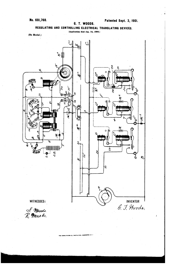
The core of the invention is a dynamotor (or electro converter)—a machine combining two electric machines on a single shaft—used as a regulator and placed in series with the main working motor to precisely control its speed without wasting power through heat (as resistors do).
1. The Power Train (Series/Shunt Configuration)
- Working Motor (D): The main motor geared to the car wheels (N).
- Dynamotor/Converter (E & F): A machine consisting of two armatures on one axis:
- Shunt-Armature (E): Connected directly across the main power lines (in shunt). This machine runs as a motor to drive the system at a practically constant speed.
- Series Armature (F): Connected in series with the armature of the working motor (D).3
- Energy Flow: The main current flows from the line, through the regulating armature (F), and then through the working motor (D).
2. Regulation by Induced Voltage (Key Innovation)
- Principle: The series armature (F) generates its own electromotive force (EMF) (voltage).4 This generated EMF is thrown into the circuit in series with the working motor (D).
- Control: The motor’s speed is regulated by varying the strength and polarity of the generated EMF from F by adjusting the resistance in the field magnets of F (using rheostats).
- Result (Speed Control without Waste):
- Slow Speed: If the generated EMF from F opposes the line voltage, the net voltage across motor D is reduced, slowing the car.
- High Speed: If the generated EMF from F aids the line voltage, the net voltage across motor D is increased.
- Efficiency: Unlike traditional resistance methods, which convert excess energy into wasted heat, this method uses one machine (E) to run the system and controls the voltage via a second machine (F), which is much more energy-efficient.
3. Operational Versatility
- The system is capable of both aiding and opposing the line current by reversing the polarity of the series armature (F), providing full, smooth control over acceleration, deceleration, and reversal.
- The system includes a low-resistance auxiliary trolley (K) circuit designed to automatically compensate for magnetic switches (G) that fail to open, improving system safety.
Concepts Influenced by This Invention
Woods’s system established foundational principles for modern electric drive control, influencing the shift away from wasteful resistive control toward efficient energy management.
- Controlled Electromotive Force (Ward Leonard Principle): Although the core idea of using a generator to vary voltage was pioneered earlier, Woods’s application and refinement of using a specialized machine (the dynamotor F) to inject a variable, controlled voltage (EMF) directly into the motor circuit influenced the design of:
- High-Precision Motor Drives: Systems requiring very smooth, precise control over speed and torque, such as cranes, elevators, and industrial presses.5
- Energy-Efficient Speed Control: The system’s central feature—avoiding the use of resistive heat for speed control—is the philosophical and engineering basis for all modern Variable Frequency Drives (VFDs) and electronic motor control systems, which prioritize efficiency and minimal power waste.
- Integrated Drive Systems (Dynamotors): The use of a dynamotor (two machines on one shaft) to perform both the driving (E) and regulating (F) functions in a compact unit influenced the design of various integrated power conversion and control modules in industrial applications.
- Redundant Safety/Auxiliary Circuits: The inclusion of an auxiliary trolley (K) and its connections to bypass failed track components influenced the design of modern power systems with built-in redundancy and fail-over mechanisms to maintain operation despite component failure.
