
Refrigerating Method and Apparatus (David N. Crosthwait, Jr., No. 1,874,912)
Patented on August 30, 1932, by David N. Crosthwait, Jr., this invention provides a unique method for refrigeration that replaces traditional mechanical piston compressors with a “hurling circuit” or liquid-jet system. Crosthwait, a pioneer in heat transfer and HVAC systems, designed this apparatus to be more efficient and simpler to maintain than the bulky, leak-prone compressors of the early 1930s.
1. The Core Concept: The Hurling Circuit
The system uses the kinetic energy of a moving liquid refrigerant to perform the work usually done by a mechanical pump.
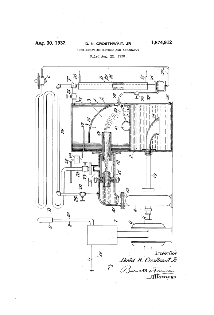
- Centrifugal Pump (4): The only major moving part, driven by an electric motor. It pulls liquid refrigerant from the bottom of the storage tank (1).
- The Jet Exhauster (E): The pump forces a high-pressure jet of liquid through a nozzle (17). As this jet shoots across the exhausting chamber (18), it creates a powerful vacuum.
- Vapor Extraction: This vacuum sucks vaporized refrigerant out of the evaporator (D) through pipe (20). The vapor is “entrained” (trapped) in the liquid jet and slammed back into the storage tank.
2. Compression and Separation
Once the mixture of liquid and vapor enters the storage tank (1), several things happen:
- Baffle Plates (21, 22): These metal plates break the force of the incoming stream, allowing the liquid to fall to the bottom while the gas rises.
- Compression: Because the tank is a closed space and the jet is constantly forcing more material in, the gas in the upper space (3) becomes highly compressed.
- Heat Transfer: The act of compressing the gas makes it hot, ready to be cooled and turned back into a liquid.
3. The Dual-Stream System
Crosthwait’s brilliance in this patent is dividing the liquid from the pump into two distinct paths to serve different needs:
| Stream Path | Destination | Purpose |
| Stream 1 | Through the Jet Exhauster (E) | Creates the vacuum to pull heat out of the refrigerator and compresses the gas. |
| Stream 2 | Through Pipe (29) to the Condenser (B) | Acts as a “carrier” to pull compressed gas into the condenser and helps liquefy it. |
- The Condenser (B): Here, the hot, compressed gas is cooled (usually by water or air) until it turns back into liquid. The liquid stream from pipe 29 helps “wash” this gas into the condenser.
4. Evaporation and Cooling
After the refrigerant is liquefied in the condenser, it travels to the Expansion Valve (C).
- Pressure Drop: The valve releases the high-pressure liquid into the low-pressure environment of the Evaporating Coil (D).
- Heat Absorption: Just as rubbing alcohol feels cold on your skin as it evaporates, the refrigerant turns into a gas inside coil D, absorbing heat from the surrounding air (the inside of the fridge).
- The Cycle Repeats: The now-warm gas is sucked back into the jet exhauster to start the process over.
5. Automation and Safety
- Thermostat (8): Placed near the cooling coil, it tells the motor when to turn on or off to maintain a steady temperature.
- Float Valve (40, 41): If the liquid level in the storage tank gets too high or low, this float automatically adjusts the flow to keep the system balanced.
- Refrigerant Types: Crosthwait suggests using chemicals like dichloroethylene or carbon tetrachloride, which were common industrial refrigerants before the widespread use of Freon.
Engineering Significance
This design was a major step toward venturi-based cooling. By using the “hurling” liquid to create a vacuum and compress gas simultaneously, Crosthwait eliminated many of the valves and seals that made 1930s refrigerators prone to breaking down. It was a rugged, “solid-state” approach to mechanical engineering.
