
Refrigerating Apparatus, Shannon L. Madison and David L. Jones, Jr., Patent No. 3,208,232
The patent by Shannon L. Madison and David L. Jones, Jr. of Rochester, New York describes a refrigerating apparatus. This invention is an field-assembled refrigeration system and a simplified method for precisely balancing the chemical refrigerant charge across remote split-system heat exchangers. By utilizing a pre-charged condensing core shipped with an intentional excess of fluid mass, the apparatus allows field technicians to purge non-condensable atmospheric gases and accurately bleed off excess refrigerant down to standard operating limits. This mass tuning process uses an exterior service manifold coupled to a flow-restricting orifice plate of calibrated dimensions, with the bleeding cycle time governed directly by a specialized pressure-versus-conduit-length metric chart.
The “Why” (The HVAC Installation Pain Point)
Prior to 1963, assembling a split-system central air conditioner or refrigerator at the point of installation was an expensive, slow, and structurally risky mechanical process. When major components like the outdoor condensing unit and the indoor evaporator core were shipped separately and piped together on-site with copper tubing, the system’s longevity depended completely on the specialized skill of a master refrigeration mechanic.
- The Special Tool Burden: Balancing the internal chemical charge required field workers to carry a delicate array of tools, including high-vacuum pumps, micron gauges, charging cylinders, weighing scales, and precision charging restrictors.
- Contamination Vulnerability: If a field tech failed to pull a deep vacuum or miscalculated the weight of the additional liquid needed to fill the varying lengths of interconnecting field pipe, atmospheric moisture and non-condensables remained trapped inside the loops. This caused acid formation in the compressor oil, high head pressures, and early compressor motor burnout.
- The Sales Bottleneck: The extreme installation costs and technical labor requirements discouraged consumer sales of split-system residential cooling units. Industry required a field-charging protocol that was fast, self-contained, and completely free from complex weighing or deep-vacuum machinery.
Inventor Section: Engineering Philosophy
Shannon L. Madison and David L. Jones, Jr. developed this system as design engineers for the Frigidaire Division of General Motors Corporation during the post-WWII housing and suburban construction boom. Operating in Rochester, New York, within a rapidly shifting industrial landscape, Madison and Jones faced the unique challenge of transitioning high-fidelity refrigeration technologies into mass-market consumer homes.
Their engineering philosophy prioritized absolute field optimization, workflow simplification, and the replacement of complex tool telemetry with clever mechanical parameters. They recognized that human error during field assembly was the leading driver of early warranty claims. By engineering a pre-charged system that used its own internal vapor pressure as a driving fluid to purge lines and balance its final operating mass, they automated a highly skilled mechanical process. This design enabled standard HVAC workers to achieve reliable factory-grade chemical charge tolerances in less than one-fourth the time of traditional methods.
Key Systems Section
High-Overcharge Sealed Condensing Unit Core
- Predetermined Excess Mass Allocation: The outdoor condensing unit core is charged at the factory with a specialized volume of lubricant and chemical refrigerant that significantly exceeds the basic normal operating requirements of the system.
- Dynamic Conduit Cushion Capacity: This factory overcharge is engineered to develop a high standby vapor pressure (often exceeding 100 p.s.i. gauge). It contains enough excess mass to fill, purge, and fully charge up to 50 feet of interconnected field-installed copper line without needing any auxiliary refrigerant canisters at the site.
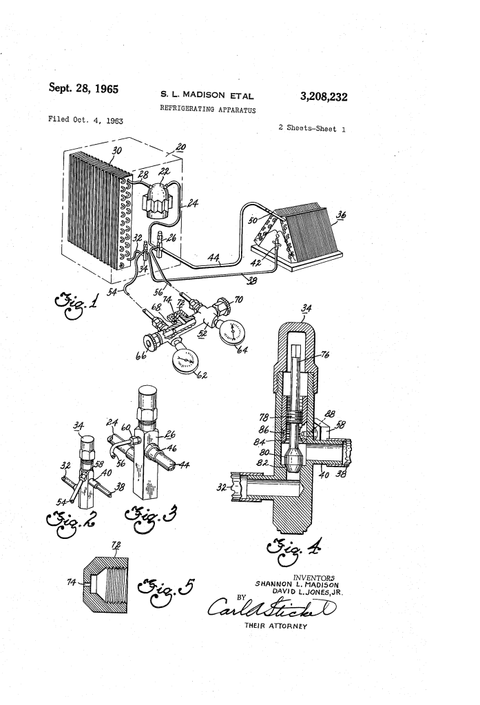
- Hermetic Component Isolation: The compressor and condenser remain isolated from the open atmosphere during transport by dual-seating service valves, protecting the pristine factory charge from environmental moisture.
Dual-Seating Multipurpose Port Isolation Valves
- Independent Stem Displacement: Both the suction line valve and the liquid line valve feature a specialized double-seating valve design. An intermediate threaded portion on a rotatable valve stem allows a field tech to move a double-sided valve plug axially between a lower seat and an upper seat.
- Bypass Service Access Tracking: During shipping, the plug is driven against the lower seat, trapping the high-pressure refrigerant within the condensing sub-loops. However, the internal passages are cast so that even when fully bottomed out, access is maintained to an exterior gauge port thread. This enables immediate pressure readings before opening the main cooling loops.
- Hermetic Operational Pass-Through: When spun to its opposite upper position, the plug seals off the service gauge port entirely. This creates a smooth, leak-free fluid channel for normal continuous refrigeration cycles.
Calibrated Orifice Metering and Purge Manifold
- Known Fluid Restriction Standard: The service manifold gauge set connects directly to the service valve ports via high-pressure flexible hoses. The central exhaust discharge line of this manifold features a specialized flare cap containing a calibrated orifice hole of highly precise dimensions.
- Atmospheric Non-Condensable Displacement: By opening the main liquid valve slightly, a high-pressure wave of raw refrigerant gas flashes out of the condenser, pushing through the field-installed evaporator loops. This action builds an internal pressure of roughly 40 p.s.i. gauge, driving out atmospheric nitrogen, oxygen, and moisture without requiring a secondary vacuum pump.
- Choked-Flow Mass Regulation: When the manifold’s suction valve is opened, the calibrated orifice allows excess refrigerant mass to bleed off to the atmosphere at a highly predictable, linear flow rate. This allows operators to track mass loss over time.
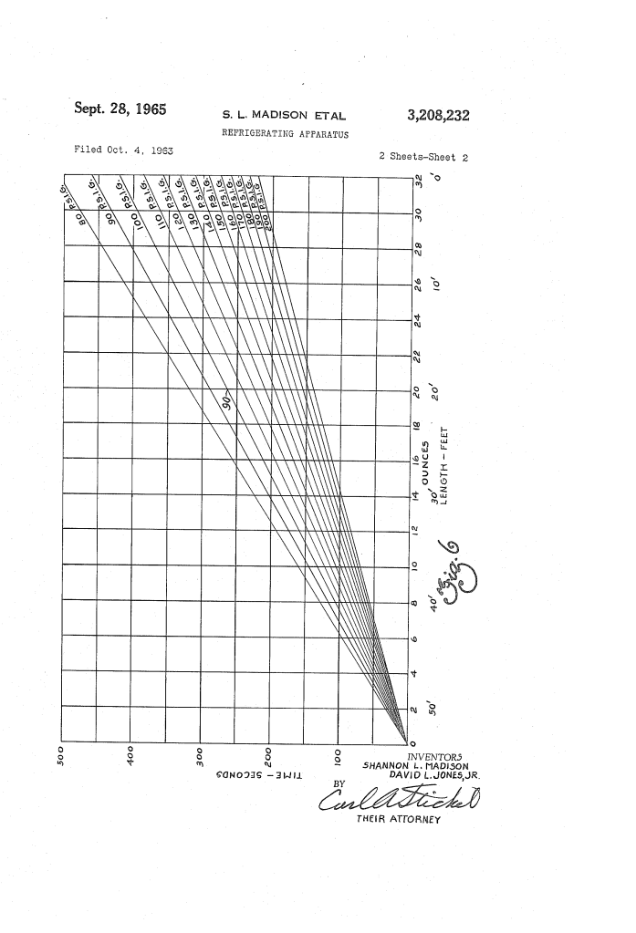
Empirical Bivariate Bleed-Cycle Time Chart
- Two-Variable Graphical Intersection: To determine the exact moment to close the purge valve, the system uses an empirical calculation chart printed with intersecting lines for liquid line length versus observed gauge pressure.
- Chronometric Fluid Tuning: The tech measures the linear length of the newly run copper lines and reads the current static pressure on the manifold’s high-side gauge. Intersecting these two values on the chart provides an exact bleed time down to the second (e.g., 262 seconds).
- Stop-Watch Mass Stabilization: The worker opens the suction manifold valve while tracking the time with a sweep-second stopwatch. Closing the valve the moment the timer hits the target leaves the refrigeration loop balanced with its ideal operating charge, completely eliminating the need for weighing scales or charging cylinders.
Comparison Table
| Technical Metric / Feature | Standard Methods of the Time (Serial Evacuation & Charging) | The New Innovation (Madison & Jones Excess-Bleed System) |
| Field Equipment Train | Required an external vacuum pump, micron gauge, charging cylinder, weighing scales, and refrigerant bottles. | None. Requires only a basic service manifold with a calibrated orifice cap and a stopwatch. |
| Primary Line Dehydration | Relied on a mechanical vacuum pump pulling structural moisture out of the open copper piping over several hours. | High-pressure gas sweeping. Uses a controlled 40 p.s.i. gauge refrigerant flash to displace air and non-condensables. |
| Charge Balancing Protocol | Adding incremental ounces of liquid mass from an auxiliary bottle through a dynamic sight-glass matrix. | Chronometric mass subtraction. Bleeding a factory overcharge through a calibrated restriction for a chart-defined time. |
| Labor-Time Coefficient | High; typically required a full multi-hour block per split-system setup by a certified technician. | Substantially compressed. Reduces overall installation time to less than one-fourth of traditional practices. |
| Internal Expansion Hardware | Demanded expensive, adjustable mechanical thermal expansion valves (TXVs) to throttle fluid rates. | Allows for ultra-simple, cost-effective fixed capillary tube or restrictor metering layouts. |
Significance Section
- Pioneered Pre-Charged Residential HVAC Architecture: This method established the modern architectural baseline for pre-charged residential split-system central air conditioning units, making residential cooling accessible to mass-market suburban home construction.
- Direct Precursor to Modern Quick-Connect Line Sets: The design concept of using isolating, multi-position valves to safely hold a factory chemical charge until final field plumbing is complete led directly to modern leak-free refrigerant quick-connect couplings and pre-evacuated line sets.
- Streamlined Modern Specialized Manufacturing Workflows: By proving that precise mass balances could be governed via empirical time charts and calibrated orifices, this patent laid early groundwork for automated, factory-floor fluid charging loops used in contemporary appliance manufacturing assembly lines.
Next Step
To evaluate the fluid dynamics of this purging process, the next step is to model the Choked-Flow Mass Discharge Velocity through the calibrated orifice cap during the bleed cycle. By applying the standard compressible gas flow equation through a restricting nozzle:
m = C_d * A * |gamma * rho_0 * P_0 * 2 / gamma + 1 ^ gamma + 1/ gamma – 1
where C_d is the dimensionless discharge coefficient of the orifice plate, A is the cross-sectional area of the calibrated opening, gamma is the specific heat ratio of the chemical refrigerant vapor, and P_0 and rho_0 define the upstream stagnation pressure and density respectively, engineers can calculate the exact fluid mass lost per second. This calculation will verify the accuracy of the empirical chart columns across varying outdoor ambient temperatures, ensuring that the timed purge consistently leaves the correct internal mass balance required for optimal compressor cooling and efficiency.
