

Reciprocal Ferrite Waveguide Phase Shifter (1966)
U.S. Patent No. 3,268,837, granted on August 23, 1966, to Frank Reggia and Howard S. Jones, Jr., addresses a major limitation in radar and high-frequency microwave communications: how to reliably shift the phase of an electromagnetic wave without introducing complex moving parts inside the wave path or requiring cumbersome, power-hungry electrical supplies.
Assigned to the United States of America as represented by the Secretary of the Army, this invention introduced an elegant mechanical alternative to electrically controlled phase shifters, delivering high stability, zero power consumption, and no physical obstruction inside the waveguide.
The Innovation: External Magnetic Field Rotation
Prior to this patent, engineers typically chose between two imperfect approaches:
- Mechanical phase shifters with moving parts inside the waveguide, which suffered from bulk, slow response speeds, signal reflection, and low phase shift per unit length.
- Electrically driven ferrite phase shifters, which relied on continuous current flowing through external magnetizing coils. Because any fluctuation in current directly altered the phase shift, these systems required heavy, expensive, and complex regulated power supplies to maintain long-term stability.
Reggia and Jones bypassed both problems by making a key discovery: changing the direction—rather than the magnitude—of an applied magnetic field relative to a centrally mounted ferrite rod shifts the phase of the microwave signal smoothly and reciprocally, completely free of signal distortion.
By utilizing rotatable external permanent magnets instead of active electrical coils, they eliminated the need for power supplies entirely while keeping moving mechanisms completely outside the microwave propagation channel.
Technical Components
The assembly combines microwave waveguide engineering with an external mechanical drive train:
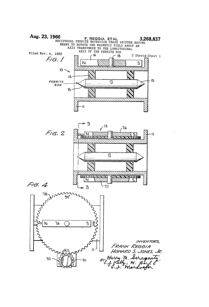
- Asymmetrical Rectangular Waveguide (11): The main transmission channel. It is dimensioned below cutoff for higher-order modes and above cutoff only for the fundamental mode, preventing unwanted wave modes.
- Centered Ferrite Rod (12): A gyromagnetic cylinder coaxially mounted along the center of the waveguide. The rod diameter is engineered to interact strongly with the RF energy while remaining small enough to prevent Faraday rotation.
- Tapered Impedance Matching Ends (15): Both ends of the ferrite rod are precision-tapered to prevent microwave reflections and ensure smooth impedance transitions.
- Dielectric Foam Supports (14): Low-loss polyfoam blocks that suspend the ferrite rod firmly along the central axis without interfering with the electromagnetic field.
- External Alnico Bar Magnets (26, 27): Mounted on opposite sides outside the waveguide walls, aligned with like poles facing one another to compress and focus the magnetic flux lines directly through the ferrite element.
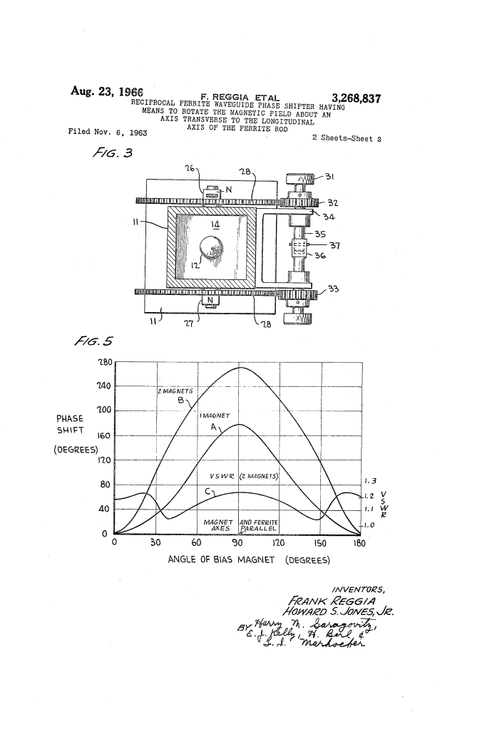
- Mechanical Drive Linkage (28, 32, 33, 35, 36, 37): A geared shaft assembly controlled by an external knob (31). A locking pin (37) in a telescoping joint allows both magnets to be rotated in lockstep or adjusted independently for precision tuning.
How the Apparatus Functions
The phase shifter operates by mechanically reorienting the external magnetic flux lines relative to the longitudinal axis of the ferrite core:
| Operational Step | Mechanical Action | Electromagnetic Result |
| 1. Zero Phase Alignment | Magnets are rotated so their N-S axis is perpendicular (90 degrees transverse) to the ferrite rod axis. | The magnetic field passes across the narrow dimension; RF permeability remains baseline and zero phase delay is introduced. |
| 2. Intermediate Adjustment | The operator turns knob 31, rotating gear discs 28 to swivel the magnets through an intermediate angle. | The longitudinal magnetic field component increases, smoothly altering the propagation constant and shifting wave phase. |
| 3. Peak Phase Delay | Magnets are brought parallel (0 degrees) to the longitudinal axis of the ferrite rod. | Maximum magnetic flux concentrates along the rod, producing the highest achievable phase shift. |
| 4. Fine Calibration | Locking pin 37 is disengaged, allowing individual rotation of gear discs 28. | Enables high-precision calibration and trimming of residual standing wave reflections. |
Performance and Empirical Results
The patent details specific performance metrics gathered on a production prototype operating at X-band:
- Operating Frequency: 9,700 mc (9.7 GHz).
- Waveguide Dimensions: 0.900 inch by 0.400 inch (standard X-band geometry).
- Ferrite Core Geometry: 2.375 inches total length, 0.270-inch diameter, with 0.5-inch matching tapers at each end.
- Magnetic Assembly: Dual 0.25 x 0.5 x 1.375-inch Alnico permanent bar magnets.
- Phase Shift Range: Smoothly adjustable from 0 degrees (perpendicular) up to large differential phase delays when aligned parallel, maintaining an exceptionally low Voltage Standing Wave Ratio (VSWR).
Historical and Scientific Impact
Developed at the U.S. Army’s Harry Diamond Laboratories, this design proved vital during the rapid expansion of Cold War radar, telemetry, and aerospace instrumentation.
- Unmatched Passive Stability: Because permanent magnets hold their field indefinitely, the unit completely eliminated phase drift caused by thermal expansion or power supply noise in active driver circuits.
- Low Insertion Loss: Keeping mechanical elements strictly outside the waveguide wall preserved signal purity and prevented internal arcing in high-power systems.
- Simplified Field Testing: Enabled rugged, portable calibration standards for military and aerospace laboratories testing phased arrays without needing active bench power.
About the Inventors
Frank Reggia was an internationally recognized microwave engineer and researcher at the Harry Diamond Laboratories (HDL) in Washington, D.C. He is widely celebrated for developing the “Reggia-Spencer” phase shifter, one of the foundational building blocks of modern electronic radar scanning and microwave signal control.
Howard S. Jones, Jr. was one of the most prolific and influential African American engineers and inventors in military electronics. During his distinguished multi-decade career at the Harry Diamond Laboratories, Jones obtained over 30 patents and published scores of foundational papers on microwave components, conformal antennas, radar fuzing, and integrated dielectric circuits. His groundbreaking antenna configurations allowed radar and guidance systems to be fitted flush onto the exterior skins of high-speed aircraft, rockets, and spacecraft.
Summary of Claims
The patent explicitly claims:
- An asymmetrical rectangular waveguide housing a coaxial ferrite rod with an external magnetic field source whose field direction rotates about an axis transverse to the longitudinal axis of the rod.
- A reciprocal microwave phase shifter utilizing one or more permanent magnets outside the waveguide to adjust phase shift purely by rotation.
- An arrangement pairing two external permanent magnets with like poles aligned to concentrate a strong field centrally through the ferrite core.
- A geared dual-magnet rotating drive with a disengageable clutch mechanism that permits both synchronized rotation and independent fine-tuning.
