
Railway Switch (1897)
U.S. Patent No. 593,665, granted on November 16, 1897, to William H. Jackson, describes an automatic safety switch mechanism designed to prevent derailments and ensure a railway track automatically returns to its main-line configuration after a train passes onto a siding. William H. Jackson, an inventor based in Indianapolis, Indiana, assigned two-thirds of his patent rights to John T. Figg, Frank M. Branthoover, and Willis F. Martin.
This specific invention solved a critical safety hazard in late 19th-century railroading: preventing catastrophic derailments caused by misplaced switches and eliminating the human error of accidentally leaving a turnout switch open after a train enters a siding.
The Core Design: The “Pivoted Switch-Table” System
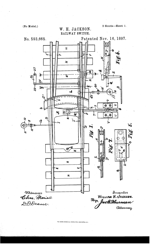
The ingenuity of Jackson’s apparatus lies in replacing traditional movable rail points with a heavy, pivoted switch-table (A) mounted directly between the main rails on a head-block (K).
- The Integral Rail Table (A)The foundation of the switch is a heavy metallic or wood-framed table (A) mounted on a central pivotal bolt (a).It carries rigid rails (D, I) and a spring-loaded pivoted spliced rail (I), which together form a continuous guide for train wheels whether the train is traveling straight or turning off.
- The Spring-Locking Mechanism (N)Mounted underneath table A is a spring-loaded switch-lock (N) containing a hinged plate (o), a foot (m), and a spiral spring (P).When the switch is set, this locking assembly holds the heavy table rigidly in alignment with either the main track (E, E) or the siding (F).
How the Apparatus Functions
The mechanism operates through an interconnected combination of hand controls, track levers, and counterweights:
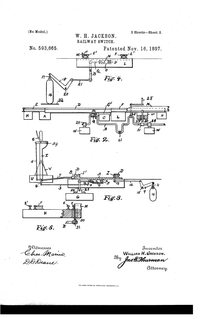
StepActionSafety Purpose1. Releasing Hand-LeverPressing hand-lever 6 toward operating-lever T actuates crank-lever S, depressing hinged plate o in lock N.Disengages the lock to allow horizontal table movement.2. Setting the SwitchThrowing operating-lever T shifts table A horizontally to align with siding rail F.Directs incoming rolling stock safely onto the siding.3. Weight ResettingAs the train passes onto the siding, its wheels depress a tapered lever (M) alongside rail F, turning crank-shaft B and raising counterweight 16.Uses the weight of the train to lift a heavy counterweight (16) resting on foundation 32.4. Automatic ReturnOnce the last truck clears lever M, counterweight 16 descends under gravity, rotating crank-shaft B and pulling table A back.Automatically resets the switch back to the main track without manual intervention.
Technical Components
Switch-Table (A): Heavy metal or composite pivot plate anchored by bolt a; guides train wheels through track transitions.
Counterweight (16): A heavy weight connected via link 17 and crank-lever 18 to crank-shaft B; heavier than table A to ensure swift, reliable return action.
Trackside Lever (M): A tapered lever mounted parallel to siding rail F; depressed by passing train wheels to charge the reset mechanism.
Signal Shaft (27): A vertical rod supporting day markers and a night lamp, rotated automatically by crank-shaft B via rod 25 to display track status.
Guide and Block (L, O): Structural supports at the swinging end of table A to maintain track alignment under heavy load.
Historical and Technical Impact
William H. Jackson’s switch system addressed major operational risks during an era of rapidly expanding railway traffic.
Fail-Safe Default: By utilizing train weight to raise a heavy counterweight, the switch guaranteed an automatic return to the main line, reducing derailments caused by open switches.
Derailment Prevention: The converging arrangement of the table rails ensured that even if a train entered a misplaced switch, the wheel flanges were safely guided without jumping the track.
Integrated Visual Signaling: Mechanically linking the signal post (27) to crank-shaft B meant signal targets instantly reflected the true physical alignment of the switch table.
About the Inventor: William H. Jackson
William H. Jackson was an inventor residing in Indianapolis, Marion County, Indiana. His contributions to track infrastructure reflect the late 19th-century push by American inventors to automate rail operations and mitigate severe accidents on high-speed lines.
Summary of Claims
The patent explicitly claims:
A pivoted switch-table provided with rigid and pivoted rails, an under-table lock, and leverage to return the switch automatically to the main line.
A crank-shaft mechanism coupled to a trackside lever (M) and counterweight (16) that uses train wheel pressure to engage the lock and reset the switch table.
An automatically operated visual target signal (27) linked directly to the switch-operating crank-shaft to show safety or danger status.
