
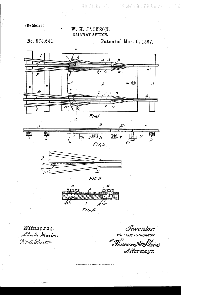
Railway Switch (1897)
U.S. Patent No. 578,641, granted on March 9, 1897, to William H. Jackson, describes a specialized safety-switch mechanism designed for railway tracks. William H. Jackson, an inventor residing in Indianapolis, Indiana, developed a system to prevent train derailments caused by misaligned switch tracks at sidings and turnouts.
This specific invention solved a persistent problem in the 19th-century railroad industry: preventing rolling stock from jumping the tracks when a switch was set for the wrong line, while allowing trains to exit sidings seamlessly regardless of how the switch was set.
The Innovation: The Pivoting Switch-Table and Spring-Rails
Traditional switches often led to catastrophic derailments if a train entered a closed or wrongly lined point. Jackson’s breakthrough was mounting the switch rails and frogs onto a heavy, centrally pivoted “table” combined with self-yielding, bevel-pointed spring-rails.
Why the Pivoting Table and Spring-Rails?
Safety & Anti-Derailment: If a train approaches from a siding against a misaligned switch, the wheel flanges physically push open spring-pressed rail points (7, 8, 9, 10), allowing the train to pass through safely without leaving the tracks.
Structural Stability: The heavy metal and timber table (A) is anchored by a central pivotal bolt (d) at the head-block (K) and supported on rollers (N, N’) at the trailing end, ensuring smooth transverse movement across sills (J, J).
Dual-Siding Versatility: It accommodates complex layouts involving both single and double sidings (F, F’ for left siding; G, G’ for right siding), enabling outward train movement from any track without manual readjustment.
Key Mechanical Components
The system is a precise assembly of moving rails and structural supports, where each part plays a critical role:
| Component | Function |
| Switch-Table (A) | The central pivoting metal/timber platform that supports the frogs and shifting rails, rotating on a main pivotal bolt (d). |
| Spring-Rails (7, 8, 9, 10) | Bevel-pointed, flexible rails normally held closed by spring pressure; they yield to wheel flanges to prevent derailments during trailing movements. |
| Shifting-Point Frogs (B, B’) | Right and left safety frogs equipped with spring-loaded shifting points (M, M’) that permit wheel flanges to pass outward. |
| Anti-Friction Rollers (N, N’) | Rollers working in recessed channels at the moving end of the table to facilitate smooth lateral travel across sills (J, J). |
| Guide-Block (L) | A curved block at the trailing end (C) that aligns the moving switch-table with stationary track rails. |
Performance: Preventing Train Derailments
Jackson’s design ensured continuous wheel flange engagement, eliminating the open gaps that typically caught wheel flanges and caused wrecks.
Operational Scenarios:
- Main-Line Through Traffic: Trains pass safely in either direction along main rails (E, E) when aligned.
- Misaligned Siding Exit: A train exiting from the left siding (F, F’) or right siding (G, G’) over a wrongly set switch forces open the spring-rails (such as 8 or 10), allowing safe passage without operator intervention.
- Siding Entry: When lined for a turnout, shifting rails (1, 2, 3, 4, 5, 6) smoothly guide incoming traffic onto the intended siding without spurning the wheel flanges.
The Manufacturing and Installation Process
Jackson outlined a clear structural assembly method for building and installing the safety switch:
- Construct the main table (A) out of heavy metal plates or a combination of metal plating and timber framing.
- Anchor the head-block (K) end centrally between the main rails (E, E) using a heavy pivotal bolt (d).
- Mount anti-friction rollers (N, N’) in limited-travel recesses beneath the curved tail end (C) over foundation sills (J, J).
- Attach the spring-loaded safety frogs (B, B’) and shifting rails (1 through 6) directly to the table surface.
- Secure the spring-rails (7, 8, 9, 10) at their butt-ends while leaving the tapered points free to flex under wheel-flange pressure.
- Connect the shifting tail end (C) to a conventional external switch stand for manual or mechanical operation.
About the Inventor: William H. Jackson
William H. Jackson was an late-19th-century American inventor based in Indianapolis, Indiana.
- Context: Operating during the rapid expansion of the American railroad network in the late 1800s, Jackson focused his efforts on infrastructure safety and mechanical reliability.
- Impact: During an era when derailments were a leading cause of property destruction and loss of life on the railways, Jackson’s design provided an economical, automatic safeguard for rail yards and busy junction points.
- Legacy: His work contributed to the broader evolution of automatic trailing switches and flexible spring-frog designs that became essential to modern railway engineering.
Summary of Claims
The patent explicitly claims:
- A railway safety switch combining a heavy switch-table pivoted at one end by a central bolt and supported on rollers at the opposite end.
- The integration of spring-pressed bevel-pointed rails (7, 8, 9, 10) that yield to wheel flanges to prevent derailment on misaligned tracks.
- The arrangement of right and left safety frogs (B, B’) with flexible points operating in combination with fixed main rails and siding tracks.
