
Railway Signal Apparatus (David Baker, No. 1,053,555)
The patent by David Baker of Los Angeles, California, describes a Railway Signal Apparatus (Patent No. 1,053,555, 1913). This invention is a unified safety system designed for railways, specifically at locations where a track passes over a bridge. It integrates two critical safety checks into a single signaling unit: the physical condition of the river/stream level (to detect flood risks to the bridge) and the status of a nearby siding switch (to prevent derailments).
Inventor Background: David Baker
David Baker was an African American inventor based in Los Angeles during the early 20th century. His invention addressed a major cause of train wrecks at the time: structural failure of bridges due to washouts and misplaced track switches. Before automated systems like Baker’s, these hazards often went undetected until a train was already upon them. Baker’s design utilized electrical circuit logic and hydro-mechanical sensors to provide a real-time warning system, showcasing a sophisticated grasp of fail-safe engineering.
Invention and Mechanism (Simplified)
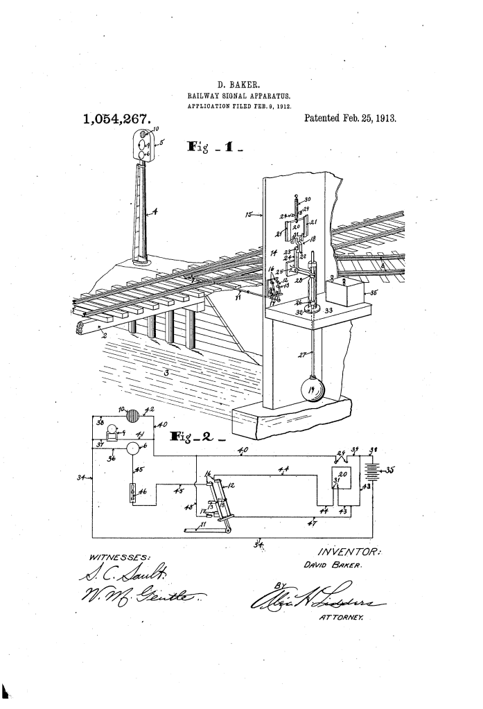
The apparatus uses a central signal box that displays a “Safe” or “Danger” signal based on the inputs from two separate sensors.
1. The Switch Sensor (Track Status)
- Rod (11) and Switch (12): A mechanical rod is connected to the siding track’s switch.
- Electrical Contacts (16, 17): When the switch is set to the main track (Safe), the rod moves the double switch (12) to bridge the “Safe” contacts. If the switch is moved to the siding (Danger), it bridges the “Danger” contacts.
- Function: This ensures that if a switch is accidentally left open or tampered with, the signal reflects this immediately.
2. The Flood Sensor (Stream Status)
- The Float (19): Inside a housing that extends into the water, a float (19) sits on the surface of the stream.
- Bell Crank (24) and Block (20): A conductor block (20) is held in place by a hook on a bell crank (24).
- Trigger: If the water rises too high, a collar on the float’s stem hits the bell crank, releasing the hook.
- Action: A spring (30) snaps the conductor block down to bridge the contacts (29). This completes the circuit for the alarm bell and the red signal.
3. The Signaling Logic (Fail-Safe)
- Visual Signals (6, 10): The signal box uses a white light (6) for safety and a red light (10) for danger.
- Audible Signal (9): A bell sounds whenever a danger condition is detected.
- Logic: The electrical wiring is arranged so that if either the water rises or the switch is misplaced, the safety light circuit is broken, and the danger light/bell circuit is completed. This “OR” logic ensures that the engineer stops for any potential hazard.
Concepts Influenced by This Invention
David Baker’s railway signal apparatus influenced the development of multi-hazard warning systems and remote sensing.
- Sensor Fusion: Baker was a pioneer in “fusing” data from two different sources (hydro-mechanical and mechanical-track) into a single user interface (the signal box). This is a foundational concept in modern SCADA (Supervisory Control and Data Acquisition) systems.
- Fail-Safe Circuitry: The design ensures that any failure of the safety sensor (like the float being triggered) automatically breaks the “Safe” circuit, adhering to the fundamental Fail-Safe principle used in all modern industrial safety engineering.
- Flood Monitoring Infrastructure: The use of float-activated switches to monitor bridge integrity was a precursor to the sophisticated ultrasonic and pressure-transducer flood warning systems used by departments of transportation today.
- Integrated Railway Safety: Baker’s work helped move the industry toward a centralized view of safety, where the “path” is not just the tracks, but the entire environmental context (bridges, water, and switches) through which the train moves.
