
Automatic Railway-Signal (Albert B. Blackburn, No. 376,362)
The patent by Albert B. Blackburn of Springfield, Ohio, describes an improved Railway-Signal (Patent No. 376,362, 1888). This invention is a mechanical track-side trigger designed to activate signaling systems automatically as a train passes. Blackburn’s primary objective was to create a device that was directionally selective—meaning it would trigger an alarm or signal if a train approached from one direction, but remain silent if a train passed in the opposite direction. This was a critical requirement for single-track railways where signals only needed to be displayed for oncoming traffic.
Inventor Background: Albert B. Blackburn
Albert B. Blackburn was a prolific African American inventor who held several patents related to railway safety and mechanical engineering in the late 19th century. His 1888 signal was an evolution of his earlier work, focusing on making track-side hardware more durable and less prone to “false triggers.” During this era, as train speeds and frequency increased, the need for reliable, automated safety equipment was paramount. Blackburn’s mastery of linkage geometry and spring-dampened systems allowed his devices to withstand the immense physical force of a passing locomotive wheel while maintaining delicate mechanical logic.
Key Mechanical Components & Functions
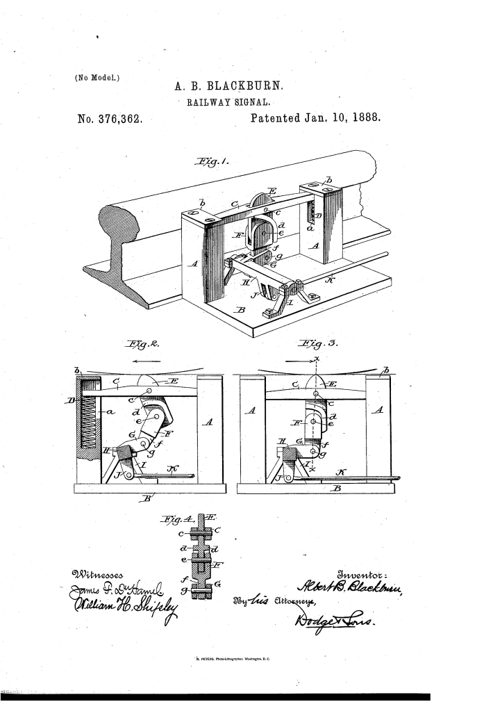
The apparatus is mounted beside the rail and consists of a spring-loaded support, a jointed trip, and a rock-shaft.
1. The Spring-Sustained Cross-Bar (C, D)
- The Frame: Two hollow upright posts (A) are secured to a base-block (B).
- The Support: A cross-bar (C) rests inside slots (a) in these posts.
- Compression: The bar is supported by coil-springs (D).
- Function: This allows the entire signaling mechanism to be depressed vertically when a heavy train wheel rolls over it. The springs ensure the device resets to its “high” position immediately after the wheel passes.
2. The Directional Trip (E) and Block (F)
- The Trip (E): A beveled “nose” or trip (E) is pivoted to the center of the cross-bar.
- The Block (F): A second piece, the block (F), is pivotally connected to the bottom of the trip, creating a “knuckle-joint.”
- The Flange (d) (Key Innovation): The trip features a flange or rib (d) on its rear edge.
- Directional Logic: This flange acts as a mechanical “one-way” stop.
- Inward Movement: If a wheel strikes from one side, the trip (E) simply rocks back on its pivot, moving the flange away from the block (F). The joint “breaks,” and no force is transmitted.
- Outward Movement: If a wheel strikes from the opposite side, the flange (d) is pressed against the block (F). This locks the two pieces into a single rigid unit.
- Directional Logic: This flange acts as a mechanical “one-way” stop.
3. The Rock-Shaft and Signal Rod (H, G, K)
- The Rock-Shaft (H): A horizontal shaft journaled in brackets.
- The Radial Arm (G): This arm is connected to the bottom of the jointed block (F).
- The Signal Rod (K): A rod connected to another arm (J) on the shaft leads to the actual signaling mechanism (such as a bell or a semaphore).
Operation: The “Directional Logic”
The device behaves differently depending on which way the train is traveling:
| Train Direction | Mechanical Action | Result |
| Non-Signal Direction (Fig. 2) | Wheel hits the bevel; Trip (E) rocks back; Flange (d) moves away from Block (F). | No Signal. The rock-shaft does not move. |
| Signal Direction (Fig. 3) | Wheel hits the Trip (E); Flange (d) presses against Block (F); Entire unit is depressed. | Signal Activated. The rock-shaft (H) rotates, pulling the rod (K). |
Improvements Over Previous Railway Signals
| Feature | Standard 1880s Signals | Blackburn’s Improved Signal |
| Directionality | Usually triggered in both directions. | Integrated knuckle-joint allows for direction-specific triggers. |
| Durability | Rigid triggers often broke under heavy loads. | Spring-sustained cross-bar (C) absorbs the vertical impact of the wheels. |
| Maintenance | Complex gear-work exposed to the elements. | Simple, robust pivot-and-flange logic that resists clogging. |
| Reliability | Prone to “chattering” or vibrating. | Pivots (c, e, g) are aligned vertically to provide a stable “trip” action. |
Significance to Railway Engineering
Albert B. Blackburn’s railway signal influenced the development of automated track safety and mechanical logic systems.
- Fail-Safe Signaling: Blackburn’s design helped formalize the use of “treadles” or “track instruments” that do not require constant human monitoring to protect single-track sections.
- Impact Absorption: The use of hollow posts with internal springs is a foundational principle in industrial shock absorption, ensuring that safety equipment survives thousands of high-velocity impacts.
- Mechanical Selection: The “jointed trip” is an early mechanical version of a logic gate (an “IF-THEN” statement), where the outcome (signal) is dependent on the input variable (direction of travel).
- Modular Integration: Because the rock-shaft (H) could be connected to any rod (K), Blackburn’s trigger was a “universal” component that could be used to ring bells, drop crossing gates, or change signal lights.
