
Railroad Switch (1897)
U.S. Patent No. 592,448, granted on October 26, 1897, to Charles Richey, describes an automatic, train-actuated railroad switch mechanism designed to allow train crews to select between the main line and a siding directly from the locomotive cab without requiring trackside workers to manually throw a ground switch. Charles Richey, an inventor based in Atlanta, Georgia, developed this mechanical system to improve both operational efficiency and safety on late 19th-century rail lines.
This specific invention solved a persistent danger and inconvenience in rail transportation: the delay and risk of sending a crew member out to set a switch manually, as well as the danger of derailment caused by improperly thrown or forgotten track switches.
The Innovation: Wheel-Actuated Tripping and Cab Control
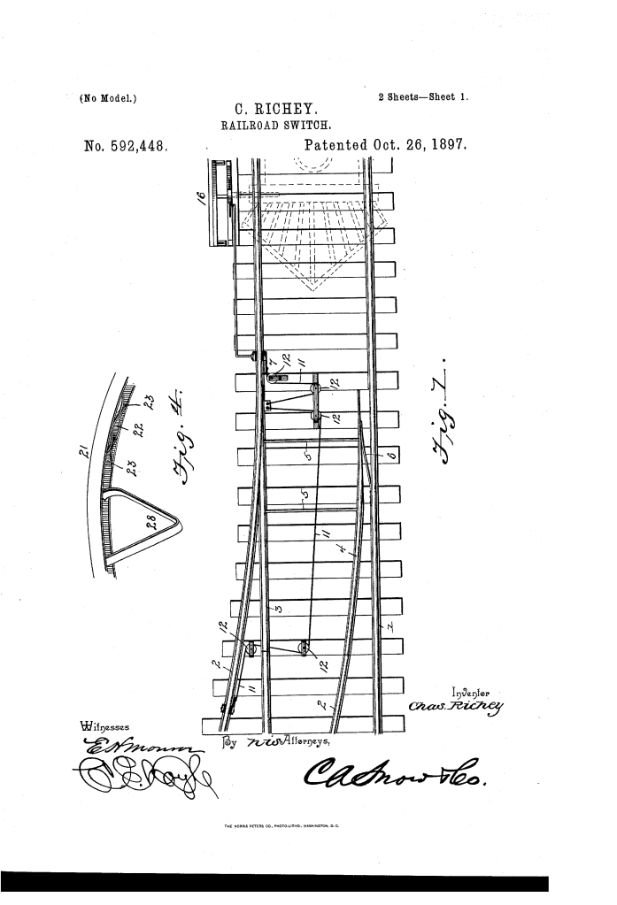
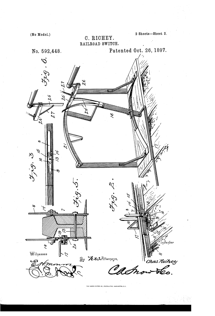
Traditional switches relied on stationary ground levers operated by switchmen. Richey’s breakthrough was a dual-action system: it combined trackside trips (7) that were depressed directly by the flange of an approaching locomotive wheel with an adjustable engine-mounted actuating arm (25) operated directly from the cab via a cord or chain (27).
This design ensured that a train could either automatically throw the switch for a siding upon approach or lock the main line open, keeping trackside workers out of harm’s way.
How the Mechanism Functions
The apparatus relies on a sequence of mechanical interlocks to route trains safely:
- Automatic Siding Entry: When the trip (7) is set in an upright position, the leading wheel of an approaching train depresses the trip arm (8). This tensioning action pulls a flexible connection (11) around direction pulleys (12), drawing the switch-rail (3) away from the main rail just as the wheel reaches the junction.
- Self-Resetting Action: An actuating spring (6) and return spring (29) force the switch back into its default position immediately after each wheel passes, maintaining tension and preventing split switches.
- Cab-Directed Main Line Locking: To lock the main track open, the engineer extends the locomotive’s actuating arm (25) to engage the long finger (24) of the switch-lever (16). Moving this lever places the trip (7) into a horizontal position, where it is secured by a spring clasp (22) out of the path of passing wheels.
- Overriding the Lock: When an approaching train needs to open the siding again, the engineer extends the actuating arm (25) to hit the shorter finger of the switch-lever. This pushes the lever past a heavy return spring (28), which snaps the switch-lever out of the clasp (22) and resets the trip (7) upright into the path of the wheels.
Technical Components
The system is built from several synchronized mechanical parts:
| Component | Function |
| Switch Rails (3, 4) | Moveable track segments connected by a switch-bar (5) to route the train to either the main track or siding. |
| Trip Assembly (7) | A pivotal lever mounted near the main rail featuring a long arm (8), a short arm (9), and a break-joint (14) that folds harmlessly if a train traverses in reverse. |
| Flexible Connection (11) | Cable or chain running through pulleys (12) that transfers the downward force of the trip directly to the switch-rails. |
| Switch-Lever (16) & Stand | A ground-mounted lever equipped with dual fingers (24) of different lengths to receive input from the locomotive’s actuating arm. |
| Spring Clasp (22) | A pair of oppositely disposed curved leaf springs (23) that form a pocket to lock the switch-lever when the main line must remain open. |
| Engine Actuator (25) | A moveable arm mounted to the locomotive’s pilot (cowcatcher), controlled via a cable (27) running into the engineer’s cab. |
Historical and Operational Impact
Richey’s design addressed key infrastructural vulnerabilities during an era of rapid expansion in American rail transport.
Safety Improvement: By installing a break-joint (14) with a stop (15) on the trip, trains exiting a siding in reverse could depress the trip without damaging the linkage or derailing.
Cost and Efficiency: It minimized the reliance on manual switchmen at low-traffic junctions and rural sidings, saving labor costs and reducing train stopping times.
Accident Prevention: The heavy spring-loaded clasp (22) prevented accidental movement or vibration-induced shifting of the track switches while high-speed trains traversed the main line.
About the Inventor: Charles Richey
Charles Richey was an African American inventor working in Atlanta, Georgia, during the late 19th century.
Patents: Richey assigned a half-interest in this patent to William Freeman, a common business practice of the era to secure funding for patent application fees and manufacturing models.
Impact: His work reflected a growing wave of late 19th-century railway safety innovations aimed at automating dangerous manual tasks, such as coupling cars and throwing track switches, which were among the leading causes of injury for railroad workers of the period.
Summary of Claims
The patent explicitly claims:
A wheel-depressible pivotal trip (7) mounted near a main-track rail and flexibly connected to yieldingly held switch-rails (3, 4).
A jointed trip arm featuring a break-joint (14) and short arm (9) with a stop (10) that allows single-direction activation while folding harmlessly under reverse travel.
A switch-lever (16) fitted with unequal-length fingers (24) operable by locomotive-mounted arms (25) to move the trip in or out of engagement via a spring clasp (22) and return spring (28).
