
Railroad Switch (1897)
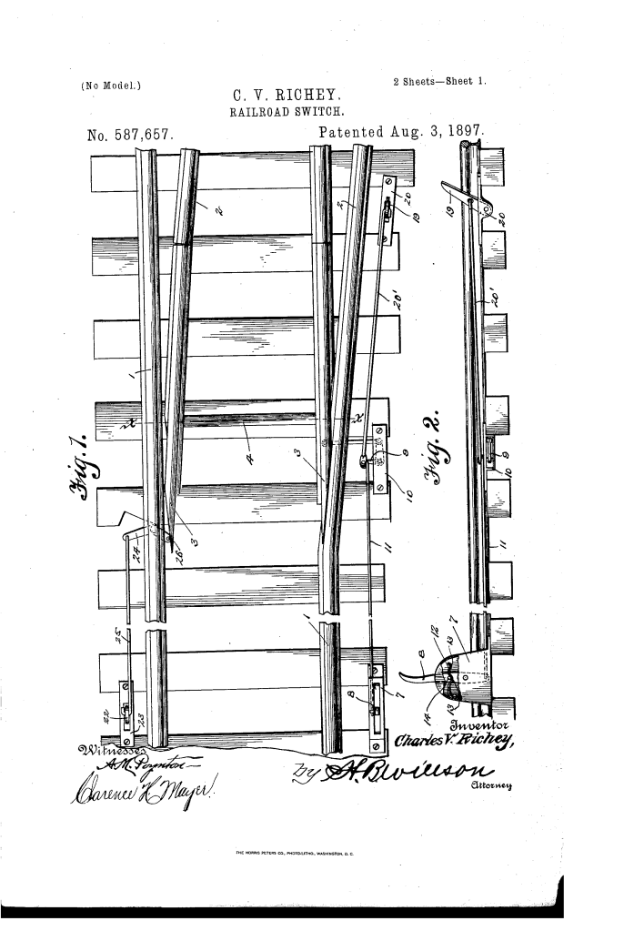
U.S. Patent No. 587,657, granted on August 3, 1897, to Charles V. Richey (assignor of one-half to Leonard C. Bailey), describes an automatic track-switching mechanism designed to allow train operators to open and close railway switches directly from the locomotive and cars without manual trackside intervention.
During late-19th-century rail expansion, manual switching was a dangerous bottleneck that required switchmen to operate levers on the ground or forced trains to make full stops. Richey, an inventor based in Washington, D.C., developed an integrated mechanical linkage system that permitted the engineer to throw the switch from the cab and ensured the track automatically reset once the train passed or backed out.
The Innovation: The Mechanical Trip-and-Lever Control
The core breakthrough of Richey’s design is its sequenced, selective mechanical engagement. By utilizing tripping arms of varying lengths and positions, the mechanism ensures that moving trains trigger the switch points only at the exact intended moments of entry and clearance.
- Anti-Friction Switch Support (4, 5, 6)To allow heavy steel rail points to slide effortlessly across railway ties, Richey connected the switch-tongues (3) with a connecting bar (4) supported by anti-friction ball bearings (5) seated inside enclosed casings (6). This minimized lateral resistance and mechanical wear.
- Cab-Actuated Locomotive Tripping Arm (15, 16, 17, 18)Mounted to the front of the locomotive is a specialized bracket (15) containing a bottomless housing box (16) and a pivoted engagement arm (17). An operating cord (18) extends directly into the cab within reach of the engineer, allowing them to raise or lower the tripping arm on approach.
- The Dual-Recess Vibration Catch (12, 13, 14)Track vibrations from passing freight trains frequently caused conventional unlatched switches to slip out of alignment. Richey integrated an internal spring catch (12) featuring two distinct locking recesses (13) that firmly seat a lateral pin (14) on the main trip lever (8), locking the switch rigidly in either the open or closed position.
How the Mechanism Functions
The switching sequence relies on mechanical coordination between the locomotive, the trackside linkage, and the rear car:
| Step | Action | Mechanical Function |
| 1. Cab Engagement | The engineer pulls the cab cord (18) to raise the locomotive arm (17). | Positions the arm to strike the trackside trip lever without stopping the train. |
| 2. Switch Opening | The raised locomotive arm strikes the main trip lever (8). | Actuates the bell-crank lever (9) via pitman rod (11), shifting the switch tongues (3) onto the siding. |
| 3. Clearance & Closure | The rear car’s hinged lateral arm (21) strikes the secondary reset arm (19). | Pulls the bell crank to return the switch tongues to the main line once the train enters the siding. |
| 4. Reverse Reset | If a train backs out of the switch, its wheels/gear engage the reverse trip arm (22). | Pivots the secondary bell-crank lever (24) via rod (25), engaging vertical pin (26) to throw the switch closed. |
Key Technical Components
- Main Track Rails (1) and Siding Rails (2): The fixed rail infrastructure routed through the junction.
- Switch Tongues (3): The movable tapered rail sections that steer wheel flanges between the main line and siding.
- Primary Bell-Crank Lever (9): Mounted in bracket (10), translates longitudinal pull from pitman rod (11) into lateral track movement.
- Differentiated Reset Arm (19): A shorter trip arm positioned closer to the track; its shorter profile prevents accidental contact with the locomotive’s main arm (17), ensuring it is only triggered by the rear car’s arm (21).
- Reverse Bell-Crank Lever (24): Positioned on the opposite side of the track to safely reset the switch if a train reverses course.
Historical and Operational Impact
Charles V. Richey’s automatic railroad switch tackled several fundamental operational hazards of the late Industrial Era:
- Collision Prevention: Misaligned switches were among the leading causes of derailments and head-on collisions. The mechanical interlocks ensured the main line automatically returned to safety after a train cleared the junction.
- Operational Efficiency: Eliminating the need for trains to come to a dead stop for trackside manual switching dramatically reduced transit delays and fuel consumption.
- Switchman Safety: Ground crew switchmen faced extreme hazards working between moving train cars in rail yards. Mechanizing the process from the cab removed personnel from active track paths.
About the Inventor and Assignee: Charles V. Richey & Leonard C. Bailey
Charles V. Richey was a prolific Washington, D.C.-based inventor active during the late 19th and early 20th centuries, patenting several mechanical improvements in transportation, rail hardware, and postal equipment.
For this patent, Richey assigned a one-half interest to Leonard C. Bailey, a prominent Black entrepreneur, civil leader, and inventor in Washington, D.C. Bailey, who patented the folding bed (U.S. Patent No. 629,286) and served as a director of the Capital Savings Bank, frequently partnered with and financed promising technical innovations during a pivotal era in American infrastructure development.
Summary of Claims
The patent explicitly claims:
- The combination of switch-tongues mounted on anti-friction ball bearings with a trackside trip lever and spring-catch alignment lock.
- The specific bell-crank and pitman linkage system interconnecting the switch-tongues with trackside trip arms.
- The differentiated arm geometry (a shorter, closer reset arm) preventing premature closure by the locomotive while enabling automatic reset by the rear car.
- The cab-controlled locomotive bracket, pivoted arm, and cord assembly allowing selective switch operation from the cab.
