
Railroad-Crossing Flag Signal (Clifton M. Ingram, No. 1,533,006)
The patent by Clifton M. Ingram of Porter, Oklahoma, describes a Railroad-Crossing Flag Signal (Patent No. 1,533,006, 1925). This invention is an automated safety device designed to warn the public of approaching trains. Ingram’s primary objective was to create a signal that remains concealed within a protective housing and only descends into view when a train is actually in motion within a specific “block” of track.
Inventor Background: Clifton M. Ingram
Clifton M. Ingram was an African American inventor who sought to solve the high rate of accidents at level crossings during the early 20th century. While basic “wig-wag” signals existed, they were often prone to mechanical failure or stayed active even when a train was stopped near a crossing, causing traffic frustration. Ingram’s design introduced a motion-sensitive logic: the signal only stays down if the train is moving, preventing false alarms and ensuring the mechanical components are protected from the elements when not in use.
Key Mechanical & Electrical Systems
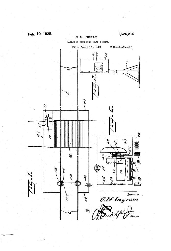
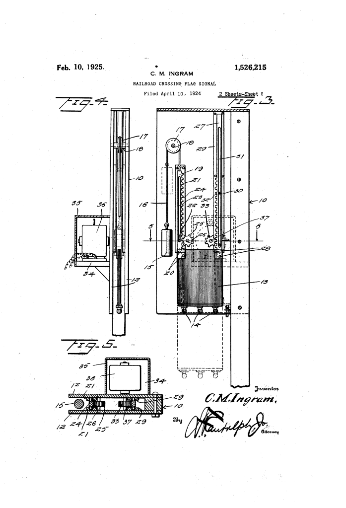
The signal consists of a vertical tower (10) containing a weighted flag (13) that is driven downward by an electric motor and retracted by gravity.
1. The Retractable Flag and Weight (13, 15, 16)
- The Flag (13): A large plate, preferably painted red and equipped with electric lamps (14).
- The Counterweight (15): The flag is naturally pulled upward into a “concealed” position inside the tower by a weight (15) connected via a cable (16) over a pulley.
- Gravity Safety: If the motor loses power or the train stops, the weight automatically pulls the flag back into the housing, keeping it out of the way of traffic.
2. The Dual Rack and Pinion Drive (24, 27, 33, 36)
- Bar 19 (Left): Features a rack (24) that meshes with an idler gear (25) to keep the flag steady and level as it moves.
- Bar 27 (Right): This is the drive bar. It features rack teeth (32) that extend only partway down the bar.
- The Motor (36): An electric motor drives a pinion (33) against Bar 27. Because the teeth only go so far, the motor cannot over-extend the flag; once the pinion reaches the end of the teeth, the flag stops at its perfectly visible “signal position.”
3. The Centrifugal Governor Switch (42-45)
This is the most innovative feature of the patent. Instead of a simple pressure switch on the track, Ingram used a centrifugal governor mounted on the train’s axle.
- Shaft 42: As the train’s axle rotates, it spins a shaft with spring arms (43).
- Contact Rings (45): When the train moves fast enough, centrifugal force flings the arms outward, pushing contact rings (45) against the rails.
- Logic: This completes the circuit to the signal’s motor. If the train stops, the arms collapse, the circuit breaks, the motor stops, and the signal weight (15) pulls the flag back up—even if the train is still technically in the “block.”
Engineering Features and Safety Logic
| Feature | Hazard Addressed | Ingram’s Engineering Solution |
| Housing (10) | Weather and Vandalism. | Keeps the flag and lamps protected from snow, rain, and dirt until needed. |
| Partial Rack Teeth (32) | Mechanical Overstrain. | Limits the signal’s descent to a precise point, preventing the motor from stripping gears. |
| Slotted Bars (23, 31) | Swaying/Jamming. | Uses guide pins (22, 30) inside elongated slots to ensure the flag moves perfectly vertically without wobbling. |
| Spring Contact (50) | Electrical Arcing/Shock. | A spring-loaded contact for the lamps cushions the connection as the flag reaches its bottom position. |
Significance to Transit Engineering
Ingram’s “Flag Signal” was a precursor to the modern gate-arm systems used at crossings today.
- Energy Efficiency: By using a centrifugal switch on the train, the signal only consumes power when a train is moving, rather than drawing current the entire time a train sits at a station or on a siding.
- Active Night Warning: The integration of lamps that only turn on when the flag is fully deployed saved battery life while providing a high-visibility warning in the dark.
- Failure to Safety: The “Weight-to-Retract” design is a classic “fail-safe” engineering principle; if the cable snaps or the motor fails, the signal does not block the road or get stuck in a confusing half-down position.
