
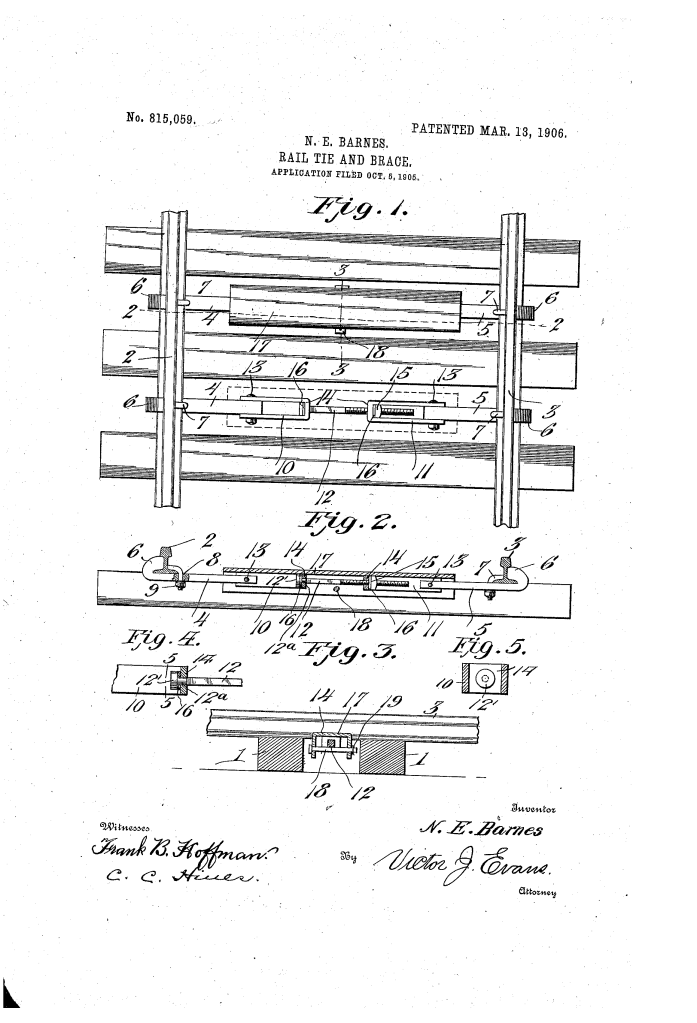
The patent by Ned E. Barnes of Willis, Texas, describes new and useful Improvements in Rail Ties and Braces (Patent No. 815,059, 1906). The object is to provide a simple, durable, and inexpensive brace for coupling the opposite rails of a rail track to prevent the rails from spreading or yielding unduly under lateral strain (especially at curves). A further object is to provide an effective shield for the connecting elements to prevent rust and accidental injury.
Inventor Background: Ned E. Barnes
Ned E. Barnes was an inventor focused on improving the durability and maintenance of infrastructure, previously patenting a Sand-Band for axles. This invention addresses a critical safety and maintenance issue in rail systems: maintaining track gauge and protecting vital coupling hardware from environmental damage.
Invention and Mechanism (Simplified)
The device is a turnbuckle-style adjustable brace that sits between the rails and is protected by a removable metal cover.
- Rail Clamping: The system uses two brace-bars (4 and 5) that extend beneath the rails (2, 3). The outer ends of these bars have hooked terminals (6) that clamp the outer side of the rail flanges.
- Clamping Bolt (7): The bars are tightened to the rails by a clamping bolt that engages the inner side of the rail’s base flange. The bolt and the slot (8) in the bar are often rectangular to prevent rotation.
- Adjustable Tie-Brace (Turnbuckle):
- Bail-Shaped Members (10, 11): The inner ends of the brace-bars connect to two bail-shaped coupling members (10, 11).
- Tie-Bolt (12) and Nut (15): The two bail members are connected by an adjustable tie-bolt (12) and nut (15).
- Function: Applying a wrench to the tie-bolt allows the length of the brace to be adjusted to the desired tension, preventing the rails from spreading. The construction allows the rails to be adjusted relatively to each other while providing bracing rigidity.
- Flexibility (Vertical Play): The connections between the brace-bars and the bail members (13) may be loose or pivotal to allow the brace members to yield vertically with the rails, permitting the rails to have a desired resiliency under load.
- Protective Shield (Key Innovation):
- Shield (17): An inverted U-shaped shield of sufficient length to cover the inner ends of the brace-bars and the adjustable coupling members.
- Fastening: The shield is secured by a simple pin (18) passing under the tie-bolt (12).
- Function: This shield protects the connecting bolt (12) and coupling members from snow, rain, rust, and accidental mechanical injury, which greatly improves the longevity and reliability of the adjustable joint.
Concepts Influenced by This Invention
Barnes’s rail brace influenced subsequent infrastructure and mechanical design by pioneering adjustable, shielded tie systems and flexible connections for rigidity.
- Shielded Adjustable Tensioners: The core concept of a turnbuckle-style tensioner (tie-bolt 12 and bails 10, 11) protected by a durable, removable housing (Shield 17) influenced the design of:
- Industrial Tie Rods: Used in construction and heavy machinery where threaded tensioning devices must be shielded from corrosion and dirt to ensure operability.
- Automotive Suspension: Components where adjustable threaded joints are covered by protective boots or shrouds.
- Rigid, Adjustable Track Gauge: The design of using robust brace-bars to maintain track gauge while allowing for precise adjustment (via the bolt 12) influenced the engineering of specialized rail components used in high-stress areas (like turnouts and curves).
- Flexible/Resilient Connections: The feature of allowing the connections (13) to be pivotal to give the rails vertical “resiliency” under load influenced the engineering philosophy of all structural ties, which must provide rigidity in one axis (lateral) while allowing for controlled flexibility in another (vertical).
- Slotted/Keyed Fastening: The use of rectangular slots (8) and bolt shanks to prevent axial rotation of the clamp is a robust mechanical principle used in heavy-duty fastening systems.
For full details of the patent go to patents.google.com
