
Propeller for Vessels (1891)
U.S. Patent No. 451,086, granted on April 28, 1891, to George Toliver, introduces an advanced screw-propeller system designed to maximize the utility of motive power. By housing a uniquely shaped propeller within a multi-stage casing, Toliver sought to eliminate the wasted energy common in open-water propellers of the late 19th century, thereby gaining speed and economizing fuel.
The invention addressed a fundamental inefficiency in maritime propulsion: the tendency of standard propellers to “slip” or scatter water outward rather than channeling it directly backward to create forward thrust.
The Innovation: The Enclosed Double-Action Propeller
Toliver’s design departed from traditional open screws by utilizing a specialized casing and a double-frustum hub with two distinct sets of spiral flanges. This setup forced the water to be processed twice as it moved through the apparatus.
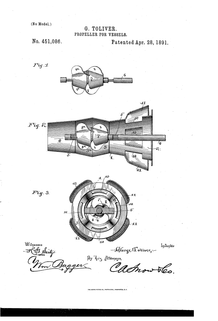
1. The Multi-Compartment Casing (1)
The water is managed through three distinct zones within the submerged casing:
- The Front Compartment (2): A funnel-shaped intake that gathers a large volume of water. It features side openings (10) protected by chutes (11) and wire netting to prevent wreckage or debris from fouling the blades.
- The Central Compartment (3, 3a): A double-conical chamber that houses the heart of the propeller.
- The Rear Compartment (4): A cylindrical or slightly tapering exit that focuses the “exhaust” water into a powerful, concentrated stream.
2. The Double-Frustum Hub (7)
The hub is shaped like two truncated cones joined at their widest bases. This geometry works in tandem with the “staggered” blades to manipulate water flow:
- Front Blades (8): Extend from the front of the hub and throw water upward and rearward past the center line.
- Rear Blades (8a): Are positioned to “break joints” with the front blades, meaning they are offset to intercept the volume of water exactly where the first set leaves off. They then drive the water forcibly downward and rearward.
How the Apparatus Functions
The propeller operates through three distinct mechanical actions to ensure that almost no energy is lost to turbulence:
| Step | Action | Mechanical Result |
| Intake | Water enters the flaring funnel and side chutes. | Ensures a constant, heavy volume of water is available for the blades. |
| Primary Compression | The front spirals (8) drive water toward the center of the casing. | Initial momentum is established. |
| Secondary Impact | The rear spirals (8a) intercept the moving water and accelerate it. | The “breaking joints” arrangement prevents water from simply spinning; it is forced backward. |
| Exhaust | Water is expelled through the rear tapering compartment. | Creates a powerful forward impetus for the vessel. |
Technical Components and Claims
- Interior Cross-Braces (5): These provide the structural support and bearings for the longitudinal shaft (6), allowing the propeller to spin smoothly within the casing despite the high pressure of the water.
- Spiral Flanges (8, 8a): Unlike standard blades, these overlap the central line of the hub, ensuring there is no “dead zone” in the middle of the propeller where water could bypass the blades.
- Chutes and Guards: A critical safety feature for 19th-century waterways, preventing the “fouling” of the propeller by wood, ropes, or other debris.
About the Inventor: George Toliver
George Toliver was an inventor based in Philadelphia, Pennsylvania. His work on the 1891 propeller patent reflects the era’s intense focus on improving the efficiency of steam-powered vessels.
- Context: In the late 1800s, naval architecture was transitioning from paddlewheels to screw propellers. Toliver’s design was part of a sophisticated wave of “ducted” or “shrouded” propeller concepts that anticipated modern thruster technology used in tugs and heavy-lift ships today.
- Legacy: By focusing on the “economy of power,” Toliver contributed to the early science of hydrodynamics, proving that the shape of the water’s path was just as important as the shape of the blade itself.
Summary of Claims
The patent explicitly protects:
- The combination of a double-frustum-shaped hub with spiral flanges that overlap the central line.
- The specific “breaking joints” arrangement of the two sets of blades to intercept and re-propel water.
- The tripartite casing design (funnel-shaped front, double-conical center, and tapering rear) that guides the flow for maximum thrust.
- The inclusion of side-entry chutes with wire-netting guards to protect the internal mechanism from submerged obstructions.
