
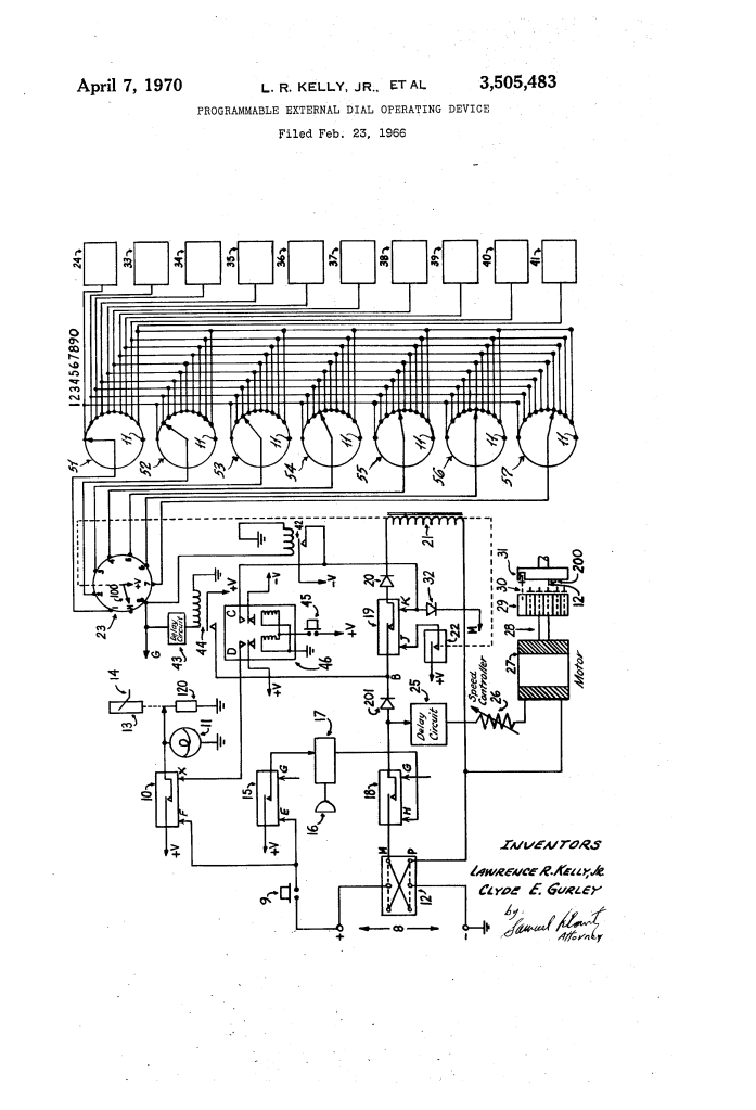
Programmable External Dial Operating Device (1970)
U.S. Patent No. 3,505,483, granted on April 7, 1970, to Lawrence Randolph Kelly, Jr. and Clyde Edward Gurley (assigned to Pelass Systems, Inc.), addresses a major regulatory and technical barrier in mid-20th-century communications: automating telephone dialing without making unauthorized electrical connections to subscriber telephone lines.
During the 1960s, telephone utility monopolies enforced strict tariffs against hardwiring non-carrier equipment directly into telephone lines. At the same time, commercial institutions, remote facilities, and home users needed a reliable way to transmit calls automatically during emergencies. Kelly and Gurley, inventors based in Washington, D.C., developed the Programmable External Lifting Automatic Sequential Selecting System (PELASSS)—an electromechanical apparatus operating completely external to the telephone instrument and line, capable of physical handset lifting, acoustic dial-tone verification, and automated sequential dialing.
The Core Design: The Non-Invasive Mechanical Interface
The central innovation of the Kelly and Gurley apparatus is its completely external, electro-mechanical coupling. Rather than injecting electronic pulses into the telephone loop, the device mimics human interaction using physical actuators and acoustic detection.
1. The Solenoid Handset Lift Mechanism (120, 13, 14)
- A primary lifting solenoid (120) drives a vertical plunger (13) coupled to an external lift arm (14).
- Upon system trigger, the lift arm physically hoists the telephone handset off its cradle hook switches, opening the line to receive the central office dial tone.
2. Acoustic Dial-Tone Verification (16, 17)
- An external acoustic microphone (16) rests adjacent to the telephone receiver earpiece.
- A sensitive signal amplifier (17) verifies the audible presence of the dial tone before dialing initiates, ensuring the system never misdials during line delays or central exchange pauses.
3. Oscillating Rotary Solenoid Carrier (27, 28, 29)
- A circular mounting plate (29) carries ten discrete plungers powered by individual solenoids (24, 33–41) aligned directly above the finger holes of the rotary wheel (31).
- A reversible DC motor and gear drive (27) rotates the entire carrier plate clockwise until the extended plunger strikes a mechanical stop (200), driving the dial forward.
How the Apparatus Functions
The sequence follows an automated electromechanical chain reaction from initial trigger to line disconnect:
| Step | Action | Functional Purpose |
| 1. Trigger | Switch 9 closes, latching relays 10 and 15 via power source 8. | Energizes solenoid 120 to hoist the handset and activates amplifier 17. |
| 2. Tone Detection | Microphone 16 detects the dial tone; amplifier 17 latches main relay 18. | Validates central office readiness before initiating physical dialing. |
| 3. Stepping Advance | Stepping switch 23 indexes wiper arm 100 to position 1 via relay 19 and coil 21. | Routes drive voltage to the solenoid pre-selected on rotary switch 51. |
| 4. Digit Insertion | Solenoid 24 energizes, driving plunger 30 into hole 1 of rotary dial 31. | Couples the motor drive mechanically to the selected digit position. |
| 5. Dial Rotation | Motor 27 turns plate 29 and dial 31 clockwise until striking stop 200. | Transmits the dialed pulse sequence into the telephone exchange. |
| 6. Reversal & Reset | Plunger trips limit switch 12, reversing motor 27 to return plate 29 to rest. | Indexes stepping switch 23 to position 2 to execute the next pre-set digit. |
Technical Components
- Manual Program Bank (51–57): Seven 10-position non-shorting rotary switches used to program any 1- to 7-digit telephone number into memory.
- Idle Selector Terminals (Position 11): Bypass contacts that allow the stepping switch to cycle through shortened numbers (such as Information “411” or Operator “0”) without energizing unneeded solenoids.
- Speed Controller (26): An adjustable rheostat regulating motor 27 to match standard human dialing velocity and exchange cadence.
- Delay Circuit (25): Suppresses premature motor rotation until the designated solenoid plunger fully seats within the dial finger hole.
- Limit Switch & Striker Lug (12, 12′): A double-pole double-throw toggle switch that alternates polarities to govern motor direction and pulse generation.
- Push-Button Keypad Adapter: An alternative stationary mounting bracket where solenoids overlie Dual-Tone Multi-Frequency (DTMF) push buttons, actuated sequentially via an oscillating sector disc.
Historical and Scientific Impact
The Kelly and Gurley patent provided an important workaround to regulatory restrictions during the evolution of the telecommunications industry:
- Tariff and Regulatory Independence: Developed while telephone companies prohibited direct electrical attachments, PELASSS operated entirely outside telephone circuitry, avoiding regulatory violations or voided equipment warranties.
- Foundation of the PELASSS Ecosystem: This patent served as the mechanical core for the inventors’ subsequent emergency communications systems, including U.S. Patent No. 3,505,476 (Automatic Telephone Alarm Apparatus), which added multi-channel voice recorders, emergency fire sensors, and automated busy-signal redialing.
- Mechanical Automation Precursor: Before low-cost integrated microprocessors and standardized modular telephone jacks became standard, the device demonstrated reliable automated sequential calling through electromechanical logic.
About the Inventors: Lawrence R. Kelly, Jr. & Clyde E. Gurley
Lawrence Randolph Kelly, Jr., and Clyde Edward Gurley were African American inventors, systems engineers, and entrepreneurs who co-founded Pelass Systems, Inc. in Washington, D.C.
Through PELASSS, Kelly and Gurley designed modular, non-invasive automated communications frameworks that converted standard consumer telephones into automated signaling instruments, laying structural groundwork for automated dialing and remote alerting systems.
Summary of Claims
The patent explicitly claims:
- An automatic telephone communication system responsive to switch closure that mechanically lifts a telephone handset from its cradle to initiate dial-tone registration.
- A plurality of electrical solenoids and energizing coils overlying each dialing position of a telephone instrument.
- Acoustic pickup and amplifying means responsive to dial-tone energy to initiate pulse generation for dialing control.
- A multi-station stepping switch operating in coordination with an array of adjustable rotary switches to sequentially energize solenoids corresponding to a pre-programmed number.
- Idle terminal contacts on the adjustable selector switches that allow skipping positions to dial numbers with fewer than seven digits.
- A reversible electric motor, carrier support, and limit-switch reversing mechanism that drives the rotary dial to its stop and resets between digits.
