
Presettable Bistable Circuits (1967)
U.S. Patent No. 3,334,245, granted on August 1, 1967, to Elbert L. Cox and Norman J. Doctor, describes an electronic bistable multivibrator designed to store preset digital data without requiring an electrical power source. Cox, based in Washington, D.C., and Doctor, based in Wheaton, Maryland, assigned the patent to the United States of America as represented by the Secretary of the Army.
This invention addressed two critical operational hurdles in military ordnance and aerospace: safely configuring electronic timers in tactical ballistic weapons before launch and preventing battery depletion during pre-flight alignment.
The Problem: Pre-Launch Power and Detonation Hazards
Tactical ballistic munitions use precise timers to detonate warheads at specific target distances calculated by fire-control computers or field observations. While electronic flip-flop timing chains offered superior accuracy and compact size compared to bulky mechanical clockwork, they introduced two severe drawbacks:
- Dud Hazards: Supplying electrical current to preset electronic flip-flops while sitting in the launcher created a parasitic drain on internal thermal or chemical batteries, risking insufficient power during flight.
- Operational Safety: Applying live electric power to an armed munition before firing raised the catastrophic danger of premature warhead detonation, threatening launch crews.
- Mechanical Wear: While mechanical rotary or toggle switches eliminated pre-launch power needs, their moving contacts were prone to contact bounce, contamination, and high-G failure under launch acceleration.
The Innovation: Passive Magnetic Inductive Unbalance
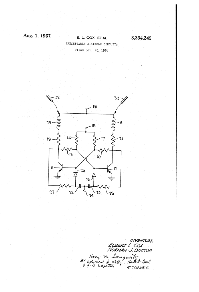
Cox and Doctor developed a zero-power presetting method that requires no mechanical switches, electrical connections, or active pre-launch current. The circuit incorporates two identical hollow-core inductors placed into the collector branches of an Eccles-Jordan flip-flop circuit.
Presetting the state of the circuit is accomplished passively by inserting a high-permeability iron or ferrite rod into the hollow core of one of the two inductors.
Why Inductive Permeability?
- Zero-Power Programming: The ferrite rod is placed physically into the core while the munition is unpowered, establishing the circuit’s memory state without battery drain.
- Controlled Asymmetry: Inserting the high-permeability rod increases the inductance of that specific coil. When launcher power is finally applied at the moment of firing, the induced transient asymmetry forces the cross-coupled transistors into a predetermined initial state (one ON, the other OFF).
- Base-Drive Dominance: Rather than relying on simple collector current choking, the surge through the cross-coupling network forces the transistor tied to the higher-inductance coil to turn fully ON (zero collector voltage).
- Transparent In-Flight Operation: Once continuous power is applied, the steady-state direct current renders the physical presence of the rod electronically inert, allowing the circuit to toggle symmetrically during countdown timing without interference.
Key Circuit Components
The circuit integrates passive magnetic biasing into an otherwise standard symmetrical transistor flip-flop:
| Component | Schematic Callout | Function in Circuit |
| Switching Transistors | 11, 12 | Matched PNP transistors in common-emitter configuration forming the bistable active pair. |
| Cross-Coupling Networks | 13, 14 and 16, 17 | Resistive voltage dividers cross-connecting each transistor collector to the opposite base to sustain complementary states. |
| Collector Load Resistors | 19, 21 | Standard load resistors wired to the primary DC collector power terminal (18). |
| Hollow-Core Inductors | 29, 31 | Identical open-core coils wired in series with each collector load resistor to receive the magnetic insert. |
| Permeability Rod | 32 | High-permeability iron or ferrite insert placed into either inductor (29 or 31) to set a 0 or 1 state. |
| Steering Network | Capacitors 22, 23; Diodes 25, 26; Resistors 27, 28 | Symmetrical triggering network routing input timing pulses from terminal 24 to cascade multiple stages into a ripple counter. |
How the Apparatus Functions
The unpowered circuit is programmed and initiated through a clean, mechanical-to-electrical sequence:
| Step | Action | Operational Purpose |
| 1. Passive Setup | Target data from a fire-control computer directs mechanical placement of ferrite rod 32 into inductor 29 or 31. | Permanently establishes the starting logic bit without drawing pre-launch current. |
| 2. Power Application | Launch command connects the primary power supply to collector terminal 18 and base terminal 15. | Energizes the circuit simultaneously at launch without operator hazard. |
| 3. Dynamic Latching | Transient base drive forces the transistor paired with the cored inductor directly into saturation (ON). | Resolves the bistable state predictably according to the magnetic rod position. |
| 4. Active Timing | Symmetrical trigger pulses enter terminal 24 to flip transistor conduction states in sequence. | Functions as an accurate binary divider or timer stage throughout ballistic flight. |
Technical and Military Impact
Assigned royalty-free for governmental use, the Cox and Doctor patent provided significant reliability benefits to Department of Defense ordnance programs:
- Complete Pre-Launch Inactivity: Shells and missiles could sit in launchers indefinitely without tethered power supplies, eliminating the logistical burden of external battery-charging harnesses.
- Personnel Safety: Because the electronic timing mechanism remains completely unpowered and quiescent during handling, accidental weapon detonation in the tube or on the rail was effectively eliminated.
- Rugged Solid-State Reliability: Dispensing with moving wiper contacts or miniature mechanical microswitches removed the primary cause of contact-bounce failures under extreme shock, vibration, and acceleration.
About the Inventors: Elbert L. Cox and Norman J. Doctor
Elbert L. Cox and Norman J. Doctor were research engineers serving with the U.S. Army’s Harry Diamond Laboratories (HDL) in Maryland and Washington, D.C.—a premier federal research center renowned for inventing the proximity fuze and advancing fluidics and microelectronics for military systems.
- Elbert L. Cox: An African American research physicist and engineer who worked extensively on solid-state electronics, timing networks, and ordnance systems, contributing key patents in non-volatile circuit initialization and electronic fuzing.
- Norman J. Doctor: A longtime supervisor and research physicist at Harry Diamond Laboratories who specialized in microminiaturization, printed circuits, and tactical electronic warfare hardware.
- Institutional Heritage: Their collaborative research at HDL helped bridge the transition from mechanical clockwork ordnance fuzes to modern digital munitions guidance.
Summary of Claims
The patent explicitly claims:
- An electronic bistable circuit containing two hollow-core inductors, where inserting a high-permeability rod into a selected inductor creates an internal unbalance sufficient to force the circuit into a specific stable state when voltage is applied, without disrupting steady-state operation.
- An Eccles-Jordan bistable multivibrator with two non-linear active elements and cross-coupling networks, featuring hollow-core inductors in series with separate load impedances to achieve power-on preset state determination via high-permeability core insertion.
- A transistorized bistable multivibrator utilizing matched common-emitter PNP stages and load resistors, wherein core-inserted inductive unbalance dictates the initial ON/OFF transistor conduction state upon power application.
