
Preset Sensitivity and Amplification Control System (1970)
U.S. Patent No. 3,518,371, granted on June 30, 1970, to Robert R. Brooks (assigned to RCA Corporation), details an advanced electro-optical feedback and signal processing control system designed for television cameras and telecine film-pickup systems. Robert R. Brooks was an accomplished electrical engineer at RCA in Camden and Moorestown, New Jersey, who specialized in television transmission equipment, video processing circuitry, and broadcast camera stabilization.
This specific invention solved a persistent and disruptive visual defect in television transmission: violent signal flashing, blooming, and transient distortion that occurred when a televised scene faded to black or experienced sudden shifts between deep darkness and bright illumination.
The Innovation: The Threshold “Preset Snap-Back” Logic
In automated broadcast camera chains, an automatic sensitivity control (ASC) circuit adjusts the camera tube’s target voltage or optical aperture to hold the video output at a standard level, while an automatic gain control (AGC) circuit boosts video amplifier gain when light fades.
When a scene darkened or a motion picture film dissolved to black, prior systems malfunctioned:
- The camera tube received no image light and began producing only spurious thermal noise and “dark current.”
- The automatic sensitivity circuit perceived this drop as under-exposure and cranked the tube’s target voltage up to its maximum sensitivity ceiling.
- Simultaneously, the AGC loop boosted amplifier gain to maximum, severely amplifying ugly background snow, streak artifacts, and camera noise.
- When the scene abruptly cut back to normal light, the pickup tube—over-sensitized and heavily saturated—blasted the electronics with an overwhelming surge of current. This created blinding white flares, severe ringing, and lingering electronic smear on television screens until the slow discharge time-constants caught up.
Brooks solved this dilemma by introducing an automatic preset logic threshold circuit. When the valid video signal drops below a designated dark threshold, the system immediately cuts the automatic control loops, snaps the pickup tube target voltage back to a predetermined nominal preset, and artificially clamps amplifier gain.
Why Preset Snap-Back?
- Transient Suppression: Because the tube is held at a safe, nominal baseline rather than maxed out, sudden restoration of scene lighting produces zero transient flashes, bloom, or overload.
- Dark-Current Squashing: Spurious noise and dark current generated during total darkness are suppressed rather than amplified.
- Smooth Recovery: As soon as genuine subject light reappears and crosses the threshold, the system re-engages automatic control smoothly from a balanced intermediate state.
Key Electronic Components
The architecture coordinates closed-loop sensing, blanking gating, and logic gating across several discrete sub-circuits:
| Component | Function |
| Pickup Device (11) | Photoconductive camera pickup tube (such as a vidicon) whose sensitivity is governed by effective cathode-to-target potential. |
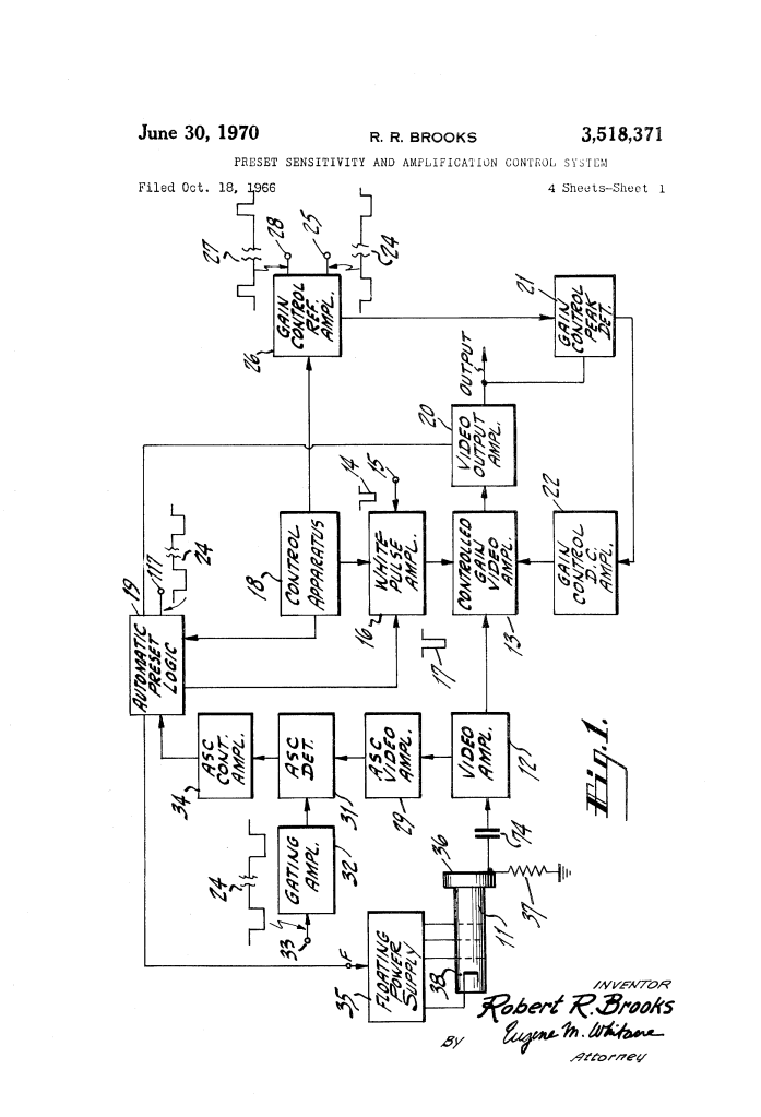
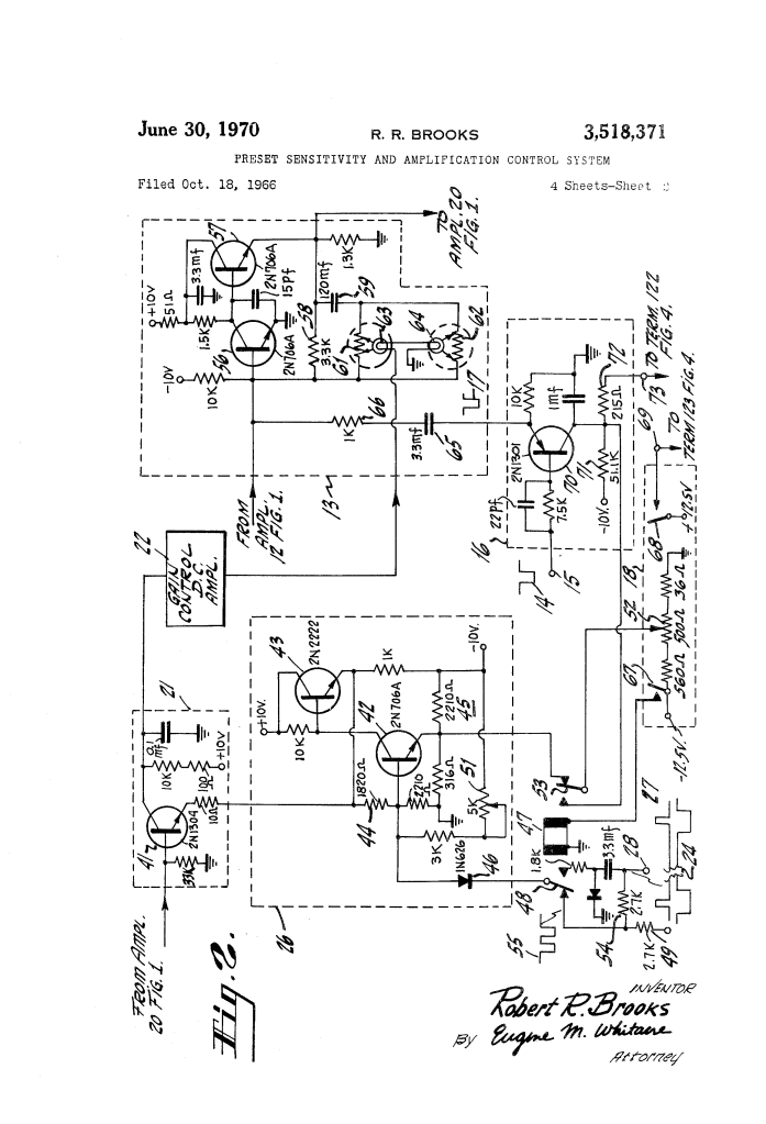
| Controlled Gain Video Amplifier (13) | Variable gain amplifier stage regulated by photo-resistive feedback elements (61, 62) and lamps (63, 64). |
| White Pulse Generator & Amplifier (16) | Injects calibrated reference pulses into the retrace blanking interval to establish an artificial ceiling for the gain control loop. |
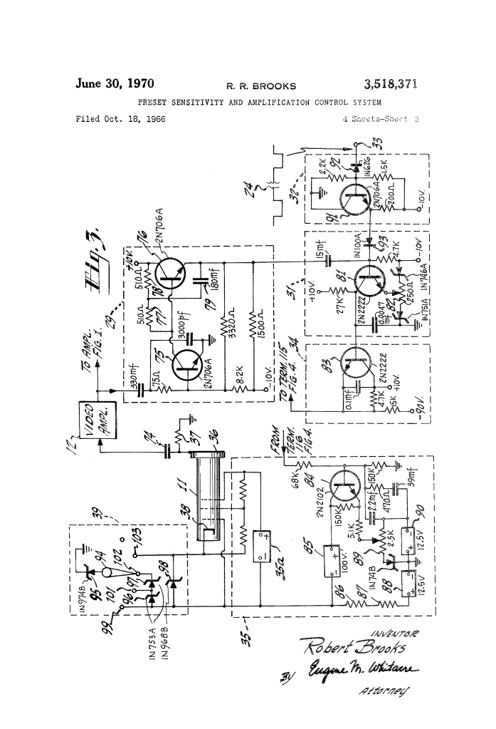
| Automatic Sensitivity Detector (31) & Amplifier (34) | Measures active trace video amplitude and outputs a DC bias across floating power supply (35) to modulate target voltage. |
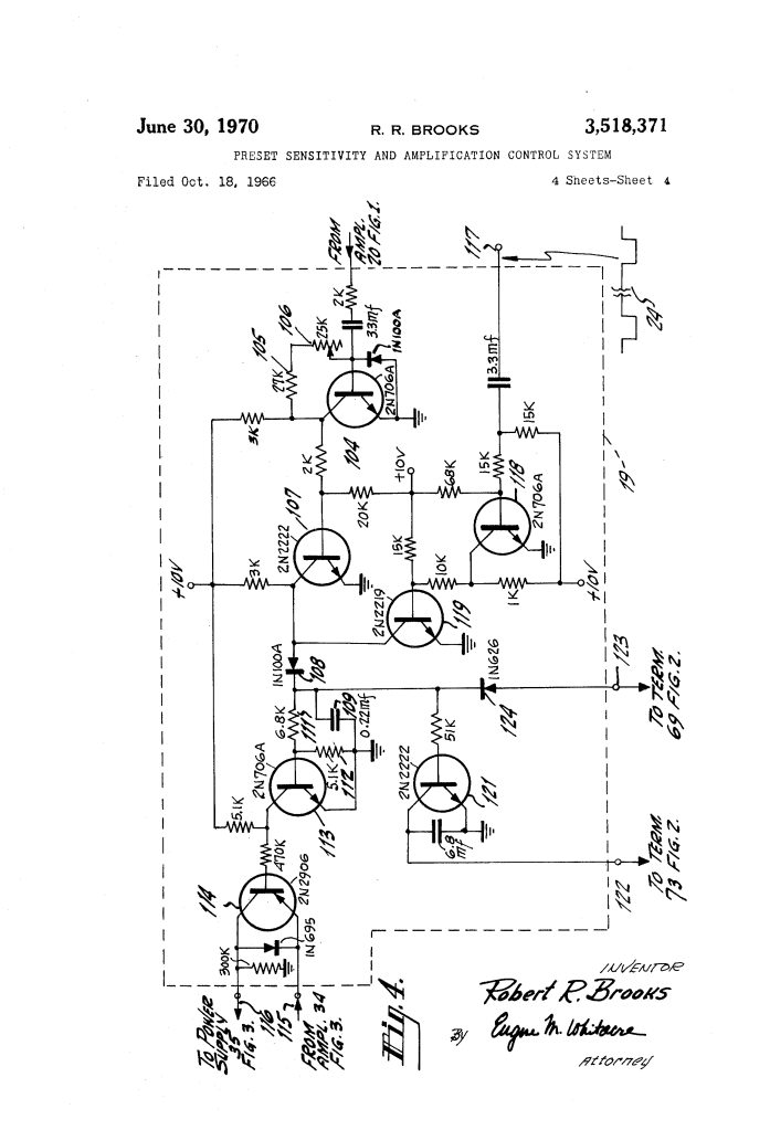
| Automatic Preset Logic Circuit (19) | Solid-state supervisory circuit that continuously monitors video level against a preset threshold via driver transistor (104) and pot (106). |
| Sensitivity Switch Transistor (114) | Solid-state series switch that instantly breaks the ASC target drive line when video drops below threshold, forcing the tube to revert to preset potentiometer (89). |
| White Level Switch Transistor (121) | Switches a reference divider in the white pulse circuit; when turned off during black fades, it forces the white pulse amplitude high, tricking the peak detector into suppressing amplifier gain. |
How the Control System Functions
The circuit continuously distinguishes between normal low-light operation and deep-black scenes, executing a protective switching sequence:
| Step | Action | Functional Purpose |
| 1. Video Level Sampling | Output video is routed to preset driver transistor 104 and compared against a bias threshold set by variable resistor 106. | Monitors active trace video while gating transistor 119 blanks out retrace pulses. |
| 2. Normal Operation | Video remains above the dark threshold; driver 104 conducts, holding transistor 107 off and firing peak detector diode 108. | Switch transistor 114 remains conductive, permitting ASC amplifier 34 to continuously regulate tube target voltage. |
| 3. Fade to Black Detection | Scene light drops below threshold; driver 104 cuts off, saturating transistor 107 and pulling detector diode 108 to ground. | Senses that the camera is viewing true blackness rather than an active picture. |
| 4. Loop Disconnection | Loss of detector output drives switch driver 113 off, cutting off PNP sensitivity switch transistor 114. | Instantly severs the target control line between ASC amplifier 34 and floating supply 35. |
| 5. Target Snap-Back | With the ASC line broken, the target control transistor 84 is governed strictly by preset potentiometer 89. | Restores pickup tube 11 to its pre-calibrated nominal sensitivity, preventing sensitivity runaway. |
| 6. Gain Suppression | Simultaneously, white-level transistor 121 turns off, ungrounding resistor 72 and boosting white pulse 17 amplitude. | Forces AGC peak detector 21 to throttle amplifier 13 gain down, silencing dark-current noise. |
| 7. Seamless Recovery | Normal scene lighting returns; video exceeds threshold, instantly turning on transistors 114 and 121. | Restores automatic closed-loop control from the nominal baseline with zero video flash or transient delay. |
Circuit Integration: Trace and Retrace Coordination
To prevent the automatic circuits from fighting each other or reacting to auxiliary timing signals, Brooks established a synchronized gating structure:
- Blanking Immunity: Gating pulses (24) applied to blanker transistor 118 disable peak detector diode 108 during horizontal retrace periods, preventing added synchronizing or white pulses from falsifying the dark-level sensing logic.
- AGC Safeguard: White pulses added during horizontal blanking are normally clamped to approximately one-third of peak white amplitude. If image video fades, the AGC loop is prevented from expanding gain beyond the limit defined by these reference pulses.
- Manual Overrides: Remote control console switches (67, 68) allow camera operators to decouple the automatic logic and control camera sensitivity and video gain manually via potentiometers without introducing system instabilities.
Historical and Technical Impact
Robert R. Brooks’ preset sensitivity and amplification control system addressed a core engineering requirement during television’s rapid post-war transition to color broadcasting and automated telecine operation:
- Telecine Film Transmission: When broadcasting 35mm and 16mm film reels, scene transitions routinely cut or dissolved to black frames. Before Brooks’ circuit, these transitions caused distracting flash artifacts and loud picture buzz on consumer television sets.
- Automated Studio Operation: By establishing autonomous solid-state threshold logic, television stations could operate film chains without a dedicated technician continuously riding the camera target and video gain knobs.
- Foundation for Broadcast Cameras: The combination of baseline snap-back and retrace reference pulse clamping influenced automatic exposure and gain architectures in subsequent generations of RCA professional studio and field cameras (such as the TK-44 and TK-47 series).
About the Inventor: Robert R. Brooks
Robert R. Brooks was an African American electrical engineer who made significant technical contributions to broadcast systems, communications engineering, and display electronics at RCA Corporation.
- Career at RCA: Brooks worked for decades within RCA’s commercial communications and broadcast divisions in New Jersey, developing specialized circuitry for television studio equipment, pulse generators, and signal processors.
- Engineering Scope: In addition to broadcast camera patents, Brooks contributed to tactical communications, radar displays, and solid-state instrumentation during RCA’s golden era of electronic innovation.
Summary of Claims
The patent explicitly claims:
- A television camera control system comprising a pickup tube, sensitivity adjusting means, and automatic sensitivity control responsive to video levels to hold signals constant.
- Limiter means responsive to a video signal falling below a selected threshold to effectively disable the sensitivity control and re-establish a pre-set nominal sensitivity.
- A solid-state switching circuit element connected in series between the sensitivity control circuit and the target voltage power supply that is rendered non-conductive when the video falls below threshold.
- A threshold amplifier and peak detector equipped with a blanking circuit to disable sensing during horizontal retrace intervals.
- Amplitude control means responsive to below-threshold video signals that concurrently acts on the video processing amplifier to attenuate spurious dark-current signals.
