
Power Line Sensing Appliance Theft Alarm (1966)
U.S. Patent No. 3,289,194, granted on November 29, 1966, to John G. King, addresses a common security problem of the mid-20th century: the rapid rise in the theft of valuable, portable household appliances like television sets and air conditioners. John G. King, an inventor based in Maywood, Illinois, developed an internal, self-contained burglar alarm designed to emit an immediate, continuous audio warning the moment a thief unplugs the appliance.
This invention solved a key limitation in consumer protection systems: how to trigger a loud, battery-powered alarm when an appliance is unplugged from the wall, without generating annoying false alarms during ordinary household electrical power failures.
The Innovation: The Power Line Sensing Bridge
Prior alarm circuits were vulnerable to simple countermeasures. Thieves routinely carried tools to slice cords or insert jumper wires, and simple power-interruption detectors suffered from a fatal operational defect: whenever municipal AC line power experienced a temporary blackout, the alarm system would mistakenly treat it as a theft and sound the horn.
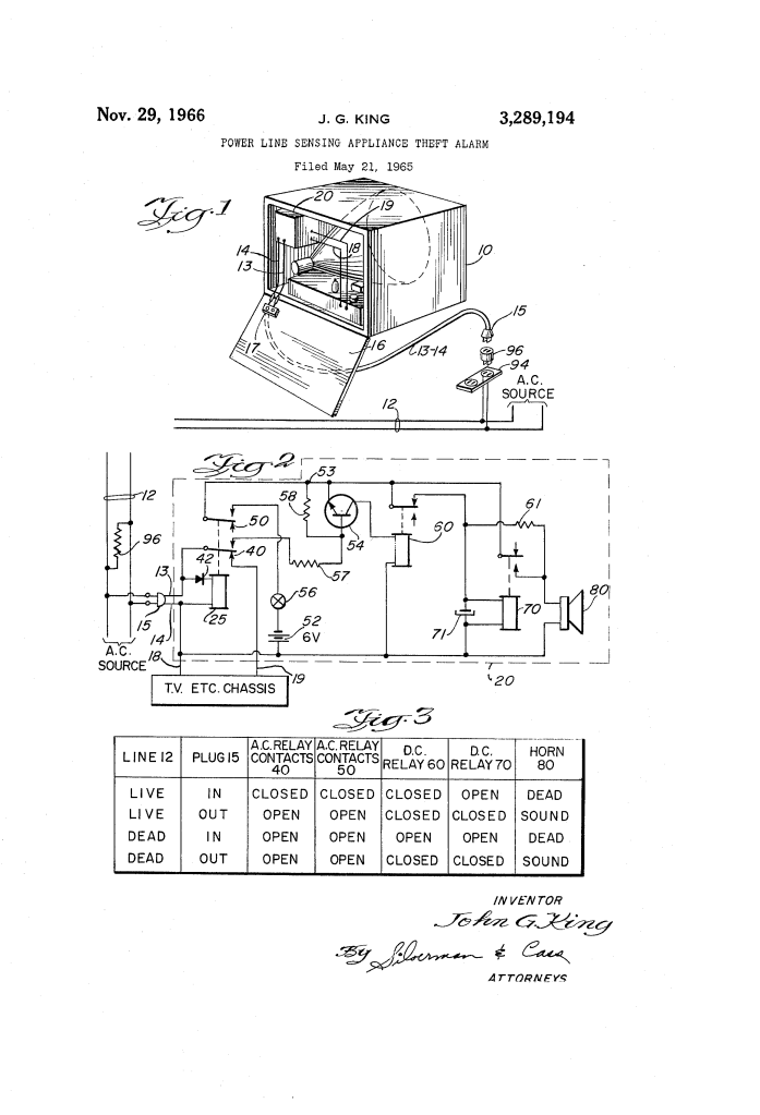
King bypassed this defect through an external sensing network: an unobtrusive, high-impedance bridging adapter installed directly across the AC wall outlet, paired with an internal sensing relay and a transistorized logic gate.
Why the Bridged Line Circuit?
- Theft vs. Power Outage Discrimination: When an AC blackout occurs while the TV remains plugged in, the external bridging resistor remains connected across the power cord prongs. This forms a complete DC control circuit that biases a blocking transistor ON, preventing the alarm from sounding.
- Unplug Triggers Alarm: When a thief pulls the plug from the receptacle, the bridge connection is physically severed. The transistor loses its forward bias, opening the pathway to the alarm horn.
- Latched Sounding: Once the horn begins sounding, an internal feedback loop maintains the circuit independently. Even if the thief attempts to cut the line, short the cord, or plug the unit back into another wall socket, the alarm horn continues blaring.
- Concealed Packaging: The circuitry is compact enough to fit entirely inside the existing chassis of a television or air conditioner, accompanied by a hidden, key-operated master switch to let authorized owners silence the unit.
Key Components
The apparatus combines AC sensing, solid-state switching, and electromechanical relay logic:
| Component | Function |
| Wall Adapter / High-Impedance Resistor (96) | An external plug adapter inserted into wall receptacle 94 containing a high-resistance bridge across the line that limits power drain while completing a DC supervisory loop. |
| Double AC Relay (25, Contacts 40, 50) | An AC-responsive relay powered via half-wave rectifier diode 42. When AC line power is present, it routes power to the TV chassis (via 40) and holds battery circuit 50 open. |
| Battery (52) & Key Switch (56) | Internal DC power supply dedicated to the alarm horn, equipped with a concealed key switch for authorized arming and disarming. |
| NPN Logic Transistor (54) | Senses continuity through bridging resistor 96. When continuity exists during a power failure, it turns ON to energize lockout relay 60. |
| Inhibit Relay (60) | Controlled by transistor 54; interrupts the battery supply to prevent the alarm from sounding during general power blackouts. |
| Delay Capacitor (71) & Horn Relay (70) | A timing capacitor that charges near-instantaneously to trip relay 70, locking battery power directly across low-impedance alarm horn 80. |
| Feedback Resistor (61) | A large resistor (e.g., 100 ohms) providing voltage-divider feedback across horn 80 (5 ohms) to keep relay 70 latched and sounding indefinitely. |
How the Apparatus Functions
The system evaluates four distinct electrical states to ensure an alarm sounds only during an actual theft:
| Operational State | Line Status & Plug Position | Internal Circuit Action | System Response |
| 1. Normal Operation | AC power ON; Plug 15 in receptacle 94. | AC relay 25 is energized. Contact 40 delivers AC to TV chassis; contact 50 disconnects battery 52. | Silent; television operates normally. |
| 2. Active Theft | AC power ON; Plug 15 pulled from wall. | AC relay 25 drops out, closing contact 50. Missing resistor 96 leaves transistor 54 OFF. Relay 60 remains unoperated; capacitor 71 charges and trips relay 70. | Alarm sounds continuously; horn latches ON via feedback resistor 61. |
| 3. Power Failure | AC power OFF; Plug 15 remains plugged in. | AC relay 25 drops out, closing contact 50. Battery DC flows through cord leads 13, 14 and resistor 96 to bias transistor 54 ON. Transistor energizes relay 60, breaking the feed to relay 70. | Silent; power loss is recognized and alarm is inhibited. |
| 4. Theft During Blackout | AC power OFF; Plug 15 pulled from wall. | Resistor 96 path is severed. Transistor 54 turns OFF, de-energizing relay 60. Battery power flows to capacitor 71 and relay 70. | Alarm sounds continuously despite the blackout. |
Historical and Scientific Impact
John G. King’s appliance alarm was developed during an era when portable televisions, hi-fi stereo consoles, and window air conditioning units represented major household investments and prime targets for residential burglary.
- Anti-Tamper Circuit Architecture: The patent introduced early consumer-level supervisory loop logic—a design standard common in high-security commercial vaults—into consumer electronics.
- Elimination of Power-Cut Vulnerability: By decoupling line-loss detection from theft detection, King prevented the nuisance alarms that plagued early consumer alarm designs during lightning storms and grid blackouts.
- Precursor to Smart Asset Protection: The underlying principle of using a signature impedance to verify physical connectivity across a shared utility connection remains a foundational concept in electronic article surveillance (EAS) and modern power-line communication (PLC) monitoring systems.
About the Inventor: John G. King
John G. King was an African American inventor and engineer based in Maywood, Illinois, an active center of midwestern industrial manufacturing and electrical engineering during the post-war era. Working as an independent developer, King focused on security apparatuses, electrical sensing networks, and circuit protection systems. His design demonstrated an economical way to package multi-stage logical discrimination (differentiating between unplugging, cable severance, and grid line failure) into consumer electronics using a minimal set of electromechanical relays and discrete solid-state transistors.
Summary of Claims
The patent explicitly claims:
- An alarm apparatus installed inside an equipment housing, comprising a high-impedance resistor connected across the AC supply line, an internal AC-responsive double-pole relay, an emergency battery, and an alarm horn.
- An inhibit circuit comprising a transistor whose base electrode connects through the external bridging resistor, causing the transistor to conduct and energize an inhibit relay during a general power failure, thereby preventing false alarms.
- A latching relay network comprising a parallel-connected delay capacitor and a high-value feedback resistor that sustains horn sounding independently once the plug is removed.
- A supervisory system where disconnecting the equipment’s line cord interrupts a continuous DC loop, instantly initiating a self-sustaining audible theft alarm.
