
Power Generating Apparatus (1968)
U.S. Patent No. 3,391,903, granted on July 9, 1968, to Charles A. Peterson, Jr., describes a marine hydro-power generating system designed to convert the intermittent kinetic energy of ocean waves into continuous electrical generation. Charles Peterson, an inventor based in Washington, D.C., developed this apparatus to overcome long-standing efficiency barriers in offshore energy harvesting.
This specific invention solved a persistent problem in marine power engineering: the intermittency of ocean waves and tides. Early ocean-energy devices relied on mechanical floats, swinging paddles, or reciprocating linkages that operated only in bursts, producing uneven mechanical torque that was difficult to couple efficiently to electrical generators. Peterson solved this by pairing a wave-overtopping capture basin with a continuous siphon-flow generation column, buffering irregular wave crests into a steady hydraulic head that constantly turns an electrical turbine.
The Core Design: The Wave-Replenished Siphon System
The core design operates by establishing a closed siphon circuit between two bodies of water at different elevations: an elevated capture reservoir positioned in the surf zone and a vertical generation tower resting in the surrounding sea.
Rather than trying to capture the rise and fall of each individual swell mechanically, Peterson captured the water itself. High-energy wave crests naturally wash over the low rim of the open reservoir, continually trapping seawater above the mean sea level. This difference in elevation creates a steady hydraulic head that drives continuous, gravity-fed downward flow through the adjacent turbine tower via siphon action.
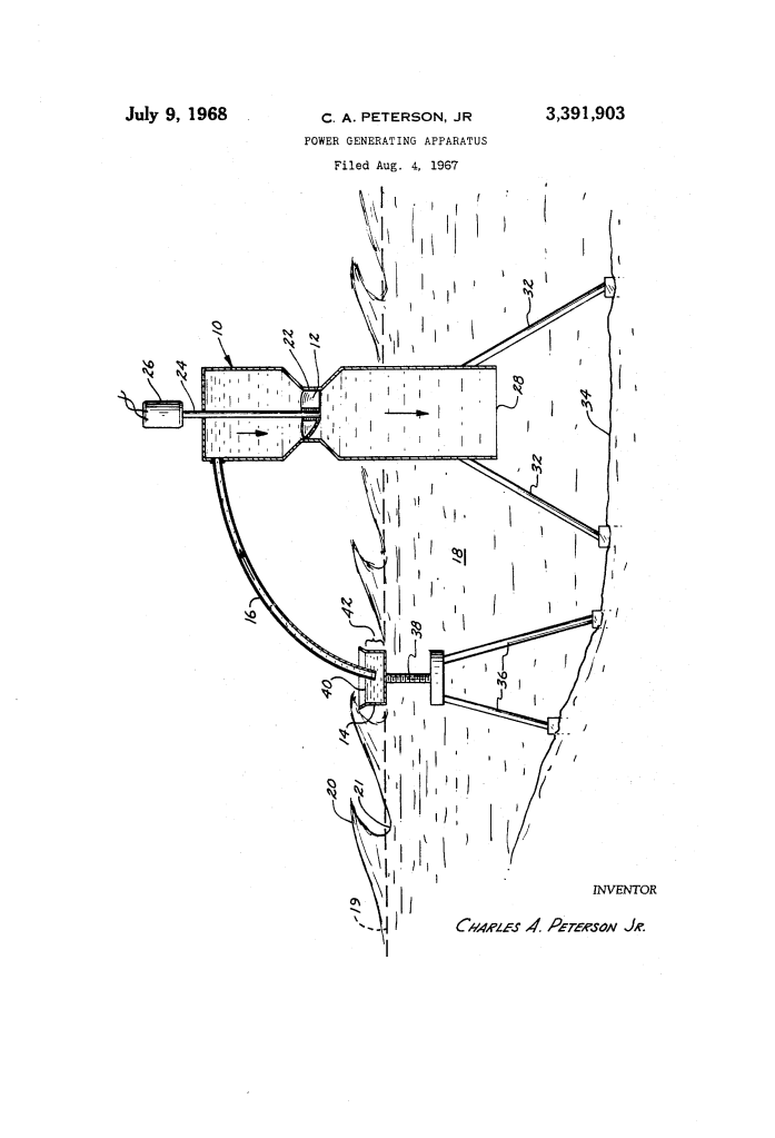
- The Catchment Reservoir (14)The reservoir is closed on all sides and the bottom, but open at the top. It is anchored in the ocean on adjustable legs (36) so that its upper rim sits slightly below the peak of incoming wave crests (20), allowing seawater to constantly splash over the sides and fill the basin to an elevated water level (40).
- The Constricted Generation Tower (10, 22)Set adjacent to the basin, a vertical tower extends deep into the sea, ensuring its bottom discharge opening (28) remains permanently submerged beneath passing wave troughs (21) so the siphon seal is never broken. The interior of the tower features a constricted throat (22) that acts as a venturi nozzle, accelerating the downward flow of water past an axial-flow turbine (12).
- The Siphon Supply Conduit (16)A sealed pipe bridges the upper portion of the elevated reservoir and the enclosed top of the generation tower. Once the system is primed with water, atmospheric pressure and the hydrostatic head drive a continuous siphon loop from the reservoir, over the crest of the conduit, and downward through the turbine.
How the Apparatus Functions
The process follows a defined operational sequence to establish and sustain uninterrupted generation:
| Step | Action | Operational Purpose |
| 1. Priming / Charging | A vacuum is drawn through supply conduit 16 to pull seawater up to the top of tower 10 and fill reservoir 14. | Establishes the continuous water column required for siphon flow. |
| 2. Wave Overtopping | Passing ocean waves 20 splash over the lip of reservoir 14, filling it to level 40. | Constantly replenishes the working hydraulic head 42 using ocean wave energy. |
| 3. Siphonic Draw | The elevation difference between reservoir level 40 and ocean level 19 induces continuous siphonic flow through conduit 16. | Pulls water out of the reservoir without relying on mechanical feed pumps. |
| 4. Velocity Acceleration | Siphoned water drops down tower 10 and accelerates through constricted venturi section 22. | Increases fluid velocity to maximize kinetic energy delivery to turbine 12. |
| 5. Power Generation | High-velocity water spins axial-flow turbine 12, driving shaft 24 and electrical generator 26. | Converts steady hydraulic flow into continuous electrical output. |
| 6. Submerged Exhaust | Discharged water exits bottom opening 28 into the ocean well below wave trough level 21. | Prevents air ingestion, maintaining uninterrupted siphon vacuum. |
Technical Components
- Generation Tower (10): Sealed vertical column mounted on seabed support legs (32), terminating in a deeply submerged discharge opening (28).
- Axial-Flow Turbine (12): Hydro-turbine positioned directly inside the high-velocity constricted section (22) of the tower.
- Catchment Reservoir (14): Open-top container positioned in the wave zone to trap incoming surf and establish mean reservoir head (40).
- Siphon Supply Conduit (16): Airtight transfer pipe connecting the water volume in reservoir (14) to the upper intake of tower (10).
- Electrical Generator (26): Power plant mounted atop or within the structure, rotated by drive shaft (24).
- Tidal Adjustment Screw (38): Variable mechanical drive on support legs (36) that raises or lowers reservoir (14) to match shifting high and low ocean tides.
Engineering and Renewable Energy Impact
Charles A. Peterson, Jr.’s configuration introduced practical advantages for coastal and offshore power development:
- Mechanical Simplicity: The system eliminated complex reciprocating linkages, oscillating floats, and delicate mechanical ratchets that were prone to heavy fouling and corrosion in marine environments.
- Continuous Baseload Flow: By buffering chaotic wave surges into a steady hydraulic reservoir, the system smoothed out peaks and lulls, supplying an even flow of water to drive standard rotational generators.
- Built-In Tidal Adaptability: Integrating mechanical height adjusters (such as screw drive 38) allowed operators to adapt the reservoir lip to varying tidal amplitudes, maintaining optimal overtopping efficiency regardless of tidal phase.
- Submerged Siphon Stability: Keeping tower discharge port 28 submerged deep below wave troughs 21 prevented air from entering the discharge line, ensuring the siphon vacuum remained unbroken during heavy ocean swells.
About the Inventor: Charles A. Peterson, Jr.
Charles A. Peterson, Jr. was an inventor based in Washington, D.C. Working in the late 1960s, Peterson focused on mechanical and fluid-power innovations, designing practical civil and hydraulic mechanisms that harnessed natural forces—such as marine wave energy and siphon pressure differentials—to generate clean, decentralized electrical power.
Summary of Claims
The patent explicitly claims:
- A wave-powered generating apparatus comprising an upright tower with a closed top and a lower end submerged below sea level, an open-top reservoir positioned to create a head of water via wave overtopping, a siphon conduit connecting the reservoir to the upper tower, and a flow-harnessing device inside the tower.
- Utilizing an axial-flow turbine mounted within a constricted velocity-increasing section of the tower to convert siphonic flow into electricity.
- A height-adjustable support mechanism connected to the reservoir to maintain optimum overtopping height across changing ocean water and tide levels.
- A self-sustaining siphon power cycle wherein continuous water evacuation through the tower is replenished exclusively by waves splashing over the open reservoir rim.
