

Postmarking and Canceling Machine (William Barry, No. 585,075)
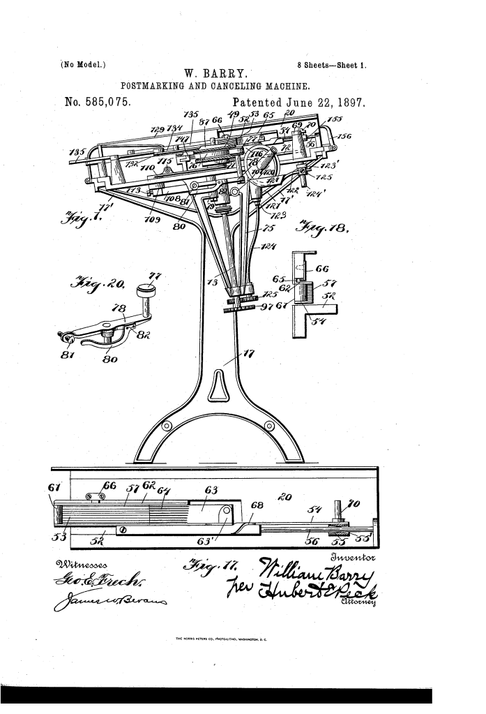
The patent by William Barry of Syracuse, New York, describes a comprehensive Postmarking and Canceling Machine (Patent No. 585,075, 1897). This highly detailed invention provides numerous improvements to create an accurate, reliable, and rapid machine capable of effectually postmarking and canceling mail-matter of various sizes and thicknesses.
Inventor Background: William Barry
William Barry was an inventor focused on mechanical automation for the postal service and commercial processing. His sustained work in the 1890s, particularly on mail-handling machinery (including the Stacking Device, No. 584,842), demonstrates his dedication to solving the crucial logistical challenge of efficiently processing massive volumes of mail in the late 19th century.
Invention and Mechanism
The machine is an intricate, synchronized system covering five stages: facing/stacking, feeding, printing, inking, and stacking the finished mail.
1. Mail Feeding and Preparation (Reciprocating Floors)
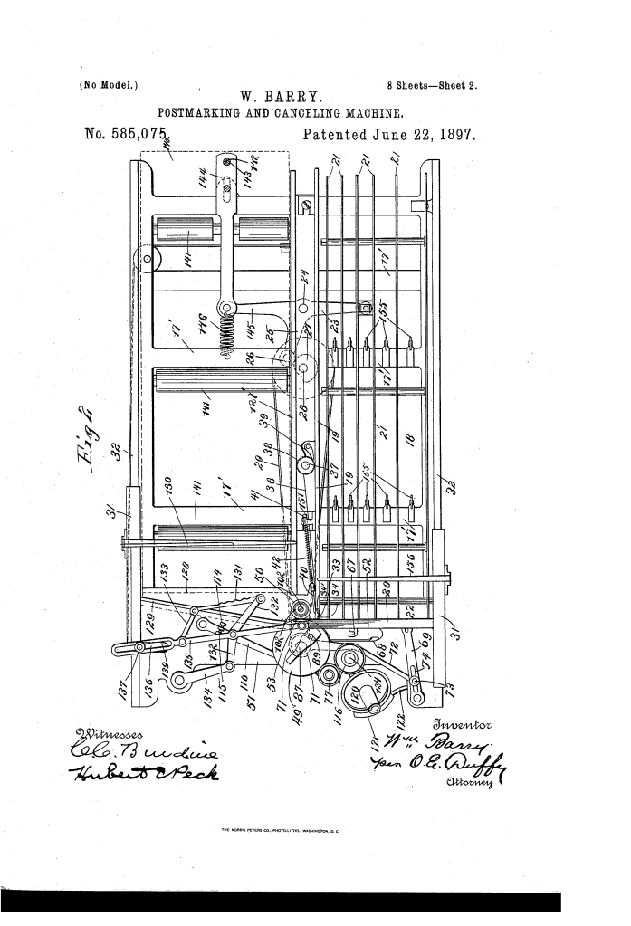
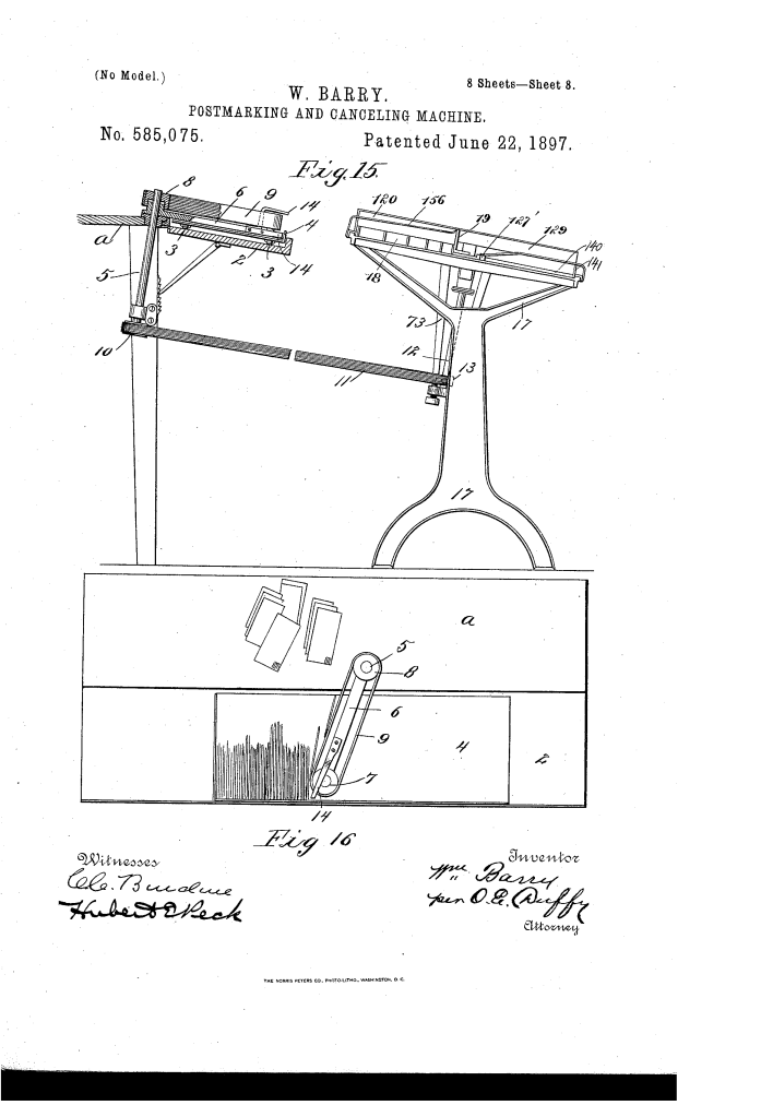
- Dual Ways: The machine has parallel feedway (18) and receiving-way (7) floors, both laterally inclined.
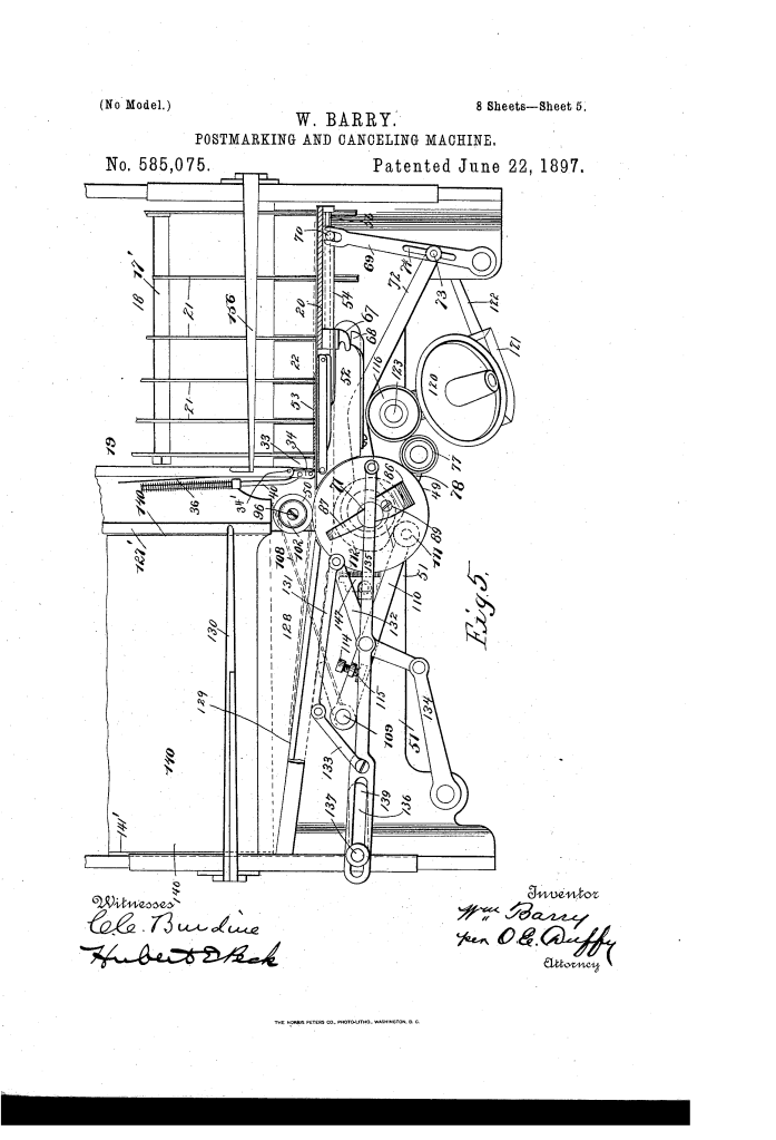
- Reciprocating Floors (Key Innovation): Both floors (rods 21, tray 107) are connected by a lever system (23) to a cam (27). The cam drives the floors to reciprocate longitudinally in opposite directions (Feedway: forward; Receiving-way: rearward).
- Function: This opposite reciprocation positively feeds the body of letters toward the print head (feedway) and feeds the stack outward (receiving-way) without crowding, reducing jamming.
2. Feeder and Separation
- Reciprocating Feeder (53): A sliding block on a carrier (54) that carries the mail laterally to the printer.
- Biting Surface: Composed of multiple independently-movable plates (57) with sharp points. This flexible surface ensures a firm grip on uneven or varied-thickness mail without damage.
- Timed Lateral Thrust: The feeder has a nose (67) that engages an external spring (68) at the start of its stroke.
- Function: This forces the feeder’s biting surface inwardly toward the letters only at the moment of engagement, ensuring it successfully pulls the letter past the separator (34) and into the rolls without bending or tearing the mail.
3. Printing Mechanism (Timed Tension)
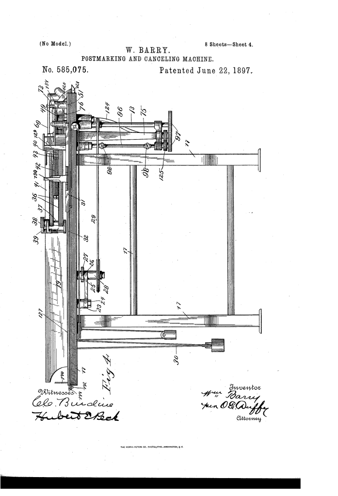
- Tension Control (Crucial Innovation): The spring pressure on the impression-roller (50) is controlled by a cam (112) on the printing-roll shaft.
- Function: The cam is timed to intermittently relieve the tension just as the letter enters the rolls (reducing friction/jar) and increase it to maximum precisely when the printing-type strikes the letter, guaranteeing a clear, solid impression.
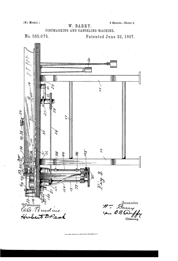
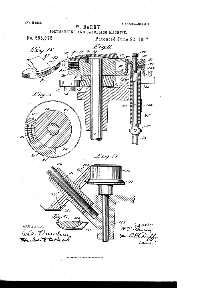
- Impression Roll (50): Features a universal or ball-joint (98) and a central hub (
) that rests in a depression (100).
- Function: This arrangement allows the impression-roll to rock laterally (yield independently of its shaft) to adapt to uneven surfaces and thicknesses of mail, ensuring a flat, solid backing for the print.
4. Inking System
- Inclined Ink-Elevating Roller (120): An inclined, beveled roller that dips into a horizontal ink-pan (121) and engages a vertical distributing roller (116).
- Function: It conveys the ink vertically from the reservoir (pan) to the distributing roller via its beveled edge, ensuring a consistent ink supply without spattering.
- Type Roll Design: The edges of the printing-roll are beveled (90) away from the type, and the printing-characters (83) are set in a circumferential groove (76).
- Function: This prevents the inking-roller from touching the letter-engaging edges of the printing-roll, ensuring no excess ink smears the rear of the mail.
5. Stacking and Containment
- Stacking Fingers: Vertical, reciprocating fingers (84) move through the receiving-way to press each printed letter forward into a stack.
- Shield (98): A flexible shield suspended over the inlet end of the receiving-way.
- Function: This shield rests on the mail stack, preventing letters from “flying up or sidewise” when discharged from the high-speed printing rolls.
- Removable Tray (140): The receiving floor is a removable tray that is constantly fed outward by the reciprocating system for easy removal and sorting.
Concepts Influenced by This Invention
Barry’s machine is a conceptual cornerstone for modern high-speed automated processing, influencing systems that require precision handling of disparate, flexible items.
- Dynamic Pressure Control (Soft/Hard Grasp): The cam-actuated, timed tension relief influenced the design of automated feeders that use dynamic pressure control to manage fragile or variable materials. This principle is vital in high-speed currency, paper, and card feeding systems to prevent crushing or tearing during entry.
- Adaptive Gripping: The feeder’s use of multiple, independently movable sections/points to conform to irregular product surfaces influenced the development of adaptive rollers, segmented grippers, and robotic end-effectors for handling non-uniform, flexible products like fabrics, paper stacks, and produce.
- Integrated Fluid/Material Transfer: The design of the inclined ink-elevating roller (120) to convey fluid from a horizontal pan to a vertical distribution roll influenced the engineering of material elevation and transfer systems (e.g., oilers, paint rollers, and chemical dosing systems) where liquid must be moved efficiently against gravity using friction.
- Vibration/Airflow Containment: The use of the flexible shield (98) to prevent turbulence or mechanical energy from disrupting the stack influenced the design of air guides, suppressors, and enclosure systems in high-speed printing and sorting machinery to maintain product order and dust control.
